GE Industrial Solutions Voltage Modules ADSVMA600D User Manual
Page 12
GEH-6250 Installation Instructions
Step 6.
After a Spectra
®
RMS Molded-Case Circuit Breaker with
microEntelliGuard
TM
or MicroVersaTrip
®
PM/Plus Trip
Unit is mounted on a Spectra
®
Series Circuit Breaker
Module, the breaker/ mounting module assembly
can be installed in the Spectra
®
Series Switchboard.
If the breaker has a breaker cable with a 12-pin
receptacle connector, plug the breaker receptacle into
the “BREAKER” 12-pin plug connector of the nearest
Distribution Cable Junction Box.
Step 7.
Spectra
®
RMS Molded-Case Circuit Breakers with
microEntelliGuard
TM
or MicroVersaTrip
®
PM Trip Units
require one additional step. You
MUST install an
auxiliary switch (microEntelliGuard
TM
Trip Units require
an auxiliary switch with gold plated contacts) in the
right accessory pouch of the breaker and route the
red and white wires of the switch to the “AUX SWITCH”
two-screw terminal block of the junction box. The
installation of this auxiliary switch will also require that
an IX filler plate (catalog number APPIW) be installed
between every Spectra
®
RMS Molded-Case Circuit
Breaker with microEntelliGuard
TM
or MicroVersaTrip
®
PM
Trip Unit.
Another use of the junction box (independent of the
Distribution Cable System) is the connection of the
neutral current sensor to any Spectra
®
RMS Molded-
Case Circuit Breaker with a microEntelliGuard
TM
,
MicroVersaTrip
®
PM or a MicroVersaTrip
®
Plus Trip Unit
that has the equipment ground fault option.
3Ø/3W
systems need no connection in order to function
properly. Wire the black and white wires of the neutral
current sensor to the “NEUTRAL CURRENT SENSOR”
two-screw terminal block on the junction box.
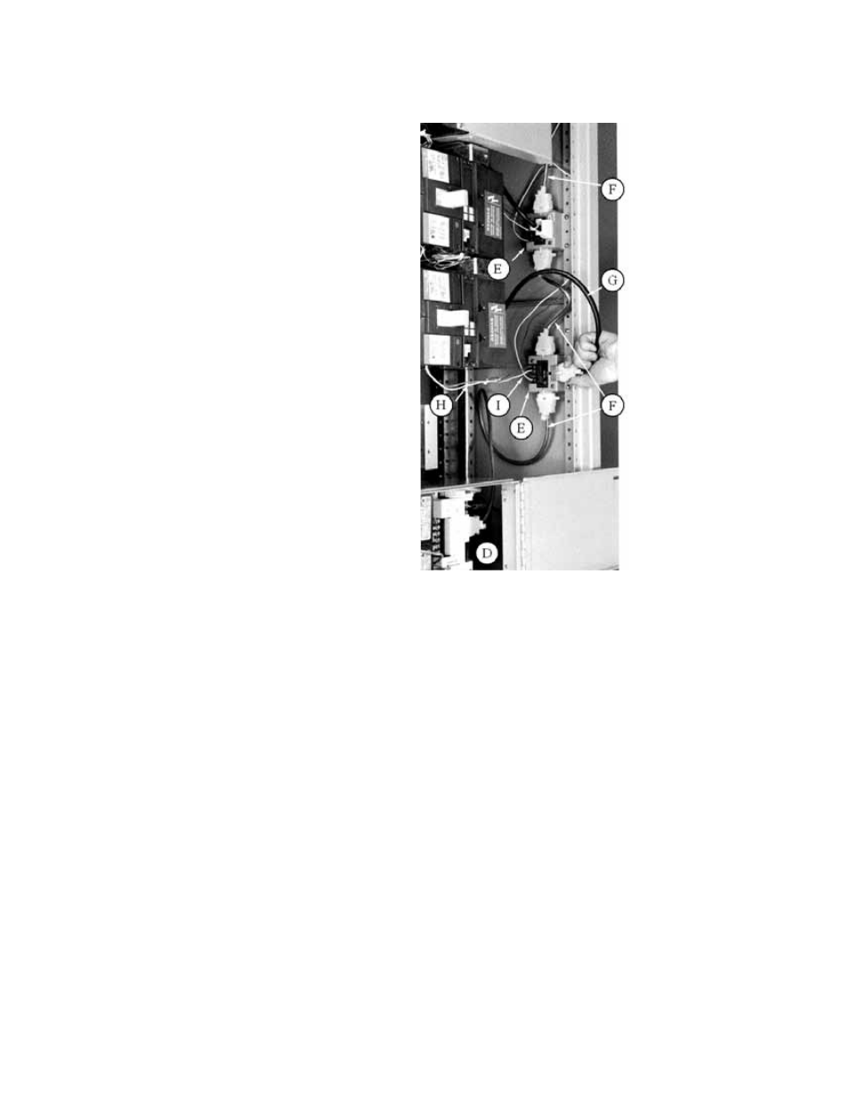
Figure 12 shows a completely wired installation of a
Spectra
®
RMS Molded-Case Circuit Breaker with a
MicroVersaTrip
®
PM Trip Unit detailing an installed
Voltage Module (D), mounted Junction Box (E),
connected Distribution Cable Harness (F), breaker
connection (G), wired auxiliary switch leads (H), and
connected current sensor wires (I).
Figure 12. Voltage Module, Spectra
®
RMS Molded-Case Circuit
Breakers with MicroVersaTrip
®
PM Trip Units and Distribution
Cable Junction Boxes installed in a Spectra
®
Series Switchboard.
Step 8.
Filler plates (J) are included with the Voltage Module to
assure a dead front and install the front plate (K) to the
supports of the 1X filler plate as shown on Figure 13.