External controller installation instructions – GE Industrial Solutions A Series Lighting Control Panelboards Installation User Manual
Page 6
External Controller Installation Instructions:
1. Connect one end on the control cable to DB25 connector on back plane first and other end of the
control cable to controller box DB25 connector. Procedure typical to other side.
2. Press the ends of the cables firmly and tighten four knurled screws of each cable ends to torque of
5-10 lb-inch.
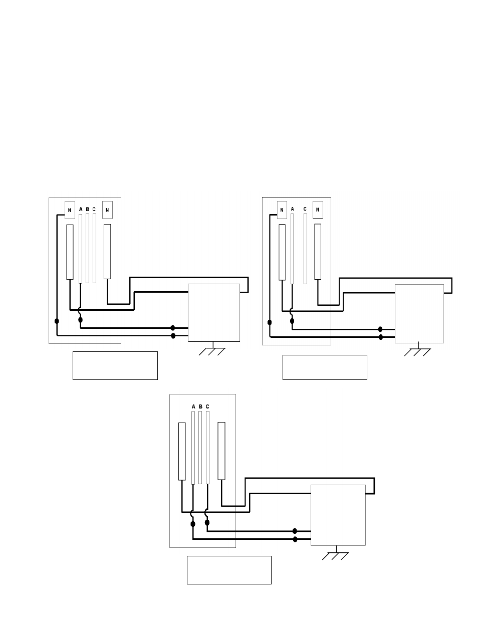
3. Connect the quick connects of Power wire (Black to Black) & Neutral wire (White to White) as
shown in schematic 1 & 2. When (No neutral) connect quick connects of power wires (black to
black) as shown in schematic 3.
4. Route the control cables, power wire & neutral wire together and fastened them with tie traps to
structure members or rails where needed for proper securement.
5. Connect the transformer secondary wires to Power in terminal at controller and torque it to 5 lb-inch.
6. Connect all the communications ports Ethernet etc to the controller.
7. Install the dead front & front cover of the Integrated Switch board
Externally mounted Controller box wire & cable schematics:
SCHEMATIC 1
( 3 Ph 4 Wire Ckt. )
CONTROLLER
BOX
CONTROL CABLE
PANEL INTERIOR
POWER WIRE
NEUTRAL WIRE
CONTROL CABLE
SCHEMATIC 2
( 1 Ph 3 Wire Ckt. )
PANEL INTERIOR
NEUTRAL WIRE
POWER WIRE
CONTROL CABLE
CONTROL CABLE
CONTROLLER
BOX
PANEL INTERIOR
SCHEMATIC 3
( 3 Ph 3 Wire Ckt. )
POWER WIRE
POWER WIRE
CONTROL CABLE
CONTROL CABLE
CONTROLLER
BOX
- 6 -