Geh-5581p2 – GE Industrial Solutions Spectra Series Power Panelboards 60 A_600 V, 100 A_240 V, 100 A_600 User Manual
Page 2
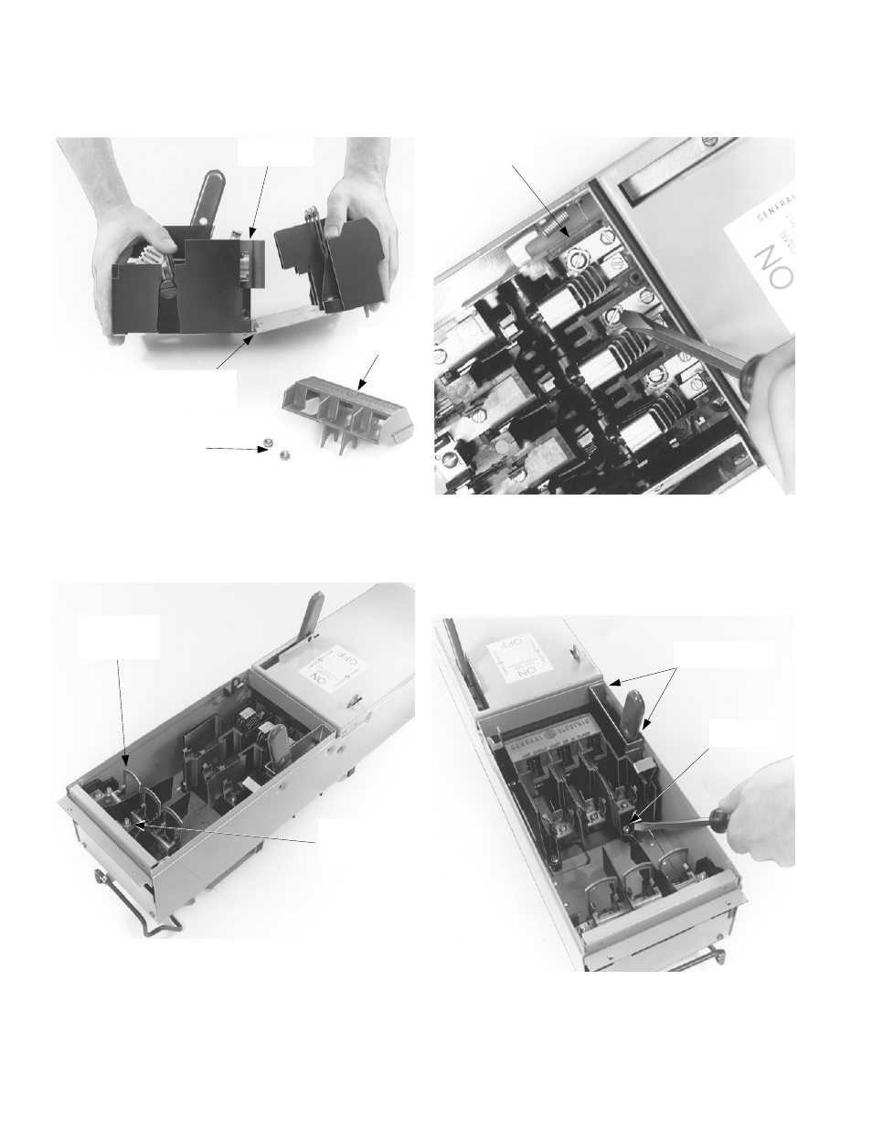
4. Prepare the switch. Remove and save the hex nuts
from the studs and red arc cover on the expansion
switch. When installing a 60- or 100-ampere, 600-volt
expansion switch, you must bend the expansion
switch unit 10 to 15 degrees, as shown in Figure 4.
Figure 4. Preparing the switch for installation.
5. Install the kit. Position the load side of the expansion
plate down into the enclosure, then place the switch
base over the connecting straps, as shown in Figure 5.
Replace the hex nuts on the plate studs and tighten
to 27–32 in-lb.
Figure 5. Install the expansion switch into the enclosure.
6. Make the electrical connections. Install #10-32 screws
with washers into the connecting straps inside the
switch base, as shown in Figure 6, and tighten the
screws to 27–32 in-lb. Replace the red arc cover onto
the switch and tighten the screws to 9–11 in-lb.
Figure 6. Making the electrical connections.
7. Install the screws. Tighten the switch base screw to
27–32 in-lb, as shown in Figure 7. Install the #10-32 x
1
/
4
" handle assembly mounting screws into the
mechanism shroud mounting holes and tighten to
27–32 in-lb.
Figure 7. Installing the handle mounting screws.
Expansion
Switch Unit
Red Arc
Cover
Bend (for 60 or 100
A, 600 V switch only,
bend 10–15°)
Hex Nuts
Insert Load
Side of Switch
(Plate) First
Install Hex
Nuts on Plate
Studs
#10-32 Screw
with Washers
Handle Assembly
Mounting Screws
Switch Base
Screw