5 bell alarm with lockout, 6 network interlock, Operation – GE Industrial Solutions EntelliGuard 800–2000 A Frames, 240–600 Vac User’s Guide User Manual
Page 19
EntelliGuard™ 800–2000 Ampere Power Circuit Breakers
Chapter 4. Accessory Operation
11
be reclosed until the blown fuse is replaced and the Open-
Fuse Lockout is reset.
The Open-Fuse Lockout is internally wired to the fuses on
800- and 1600-ampere frame breakers. On 2000-ampere
frame breakers, the Open-Fuse Lockout is wired to the
secondary disconnect as illustrated in Figure 7. The Open-
Fuse Lockout connects to the fuses in a Fuse Rollout
Element through the secondary disconnect.
Figure 7. Open-Fuse Lockout (OFLO) connections to the secondary
disconnect for EGF-20 breakers.
4.5 Bell Alarm with Lockout
The Bell Alarm with Lockout prevents closing of the
breaker after a protection trip until the Bell Alarm with
Lockout is reset. It contains a set of switch contacts to
remotely indicate that the circuit breaker has tripped
because of a protection trip. Catalog numbers for the Bell
Alarm with Lockout module and kit are given in Table 6.
For installation instructions and trouble-shooting, see
DEH238.
Kit Catalog
Number
Module Catalog
Number
EGBLALMSFKIT
EGBLALMRPLC
Table 6. Catalog numbers for the Bell Alarm with Lockout module and
kit.
Operation
The Bell Alarm with Lockout prevents reclosing of the
breaker after a trip until it is reset. The accessory is
activated and its status circuit changes state whenever the
breaker is tripped by an overcurrent, ground fault, or
protective relay function via the EntelliGuard
Messenger™. The EntelliGuard Messenger continuously
monitors the state of the status circuit. The connections of
the Bell Alarm with Lockout to the secondary disconnect
are illustrated in Figure 8. A trip caused by the manual
OPEN
button or by the Shunt Trip does not activate the
Bell Alarm with Lockout.
The Bell Alarm with Lockout can be reset by manually
depressing the yellow target/RESET button on the breaker
escutcheon. This will return the Bell Alarm with Lockout
status contact to its normal configuration and allow the
breaker to be closed.
Figure 8. Bell Alarm with Lockout connections to the secondary
disconnect. The contact is shown in the RESET state.
4.6 Network Interlock
The Network Interlock provides a means of locking out a
breaker to coordinate its operation with other breakers in
the distribution network. When activated by the
EntelliGuard Messenger™, the Network Interlock prevents
the breaker from closing. When the EntelliGuard
Messenger issues a RESET signal, the breaker is able to
close either remotely or locally. The Network Interlock
contains a set of switch contacts to remotely indicate the
state of the lockout and, thus, whether or not the breaker
can be closed. Catalog numbers and the operating voltage
for the Network Interlock are listed in Table 7. For
installation instructions and trouble-shooting, see
DEH41119. The Network Interlock accessory is only
available on electrically operated breakers.
Kit Catalog
Number
Module Catalog
Number
Voltage Rating
EGNTWKSFKIT
EGNTWKSFRPLC 120 Vac, 60 Hz
Table 7. Catalog numbers and operating voltage for the Network
Interlock accessory.
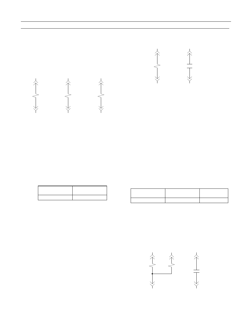
Operation
The Network Interlock consists of a set circuit, a reset
circuit, and a status circuit. The device connections to the
secondary disconnect are shown in Figure 9. Note that a
Bell Alarm with Lockout and a Network Interlock cannot
be installed concurrently in a breaker.
Figure 9. Network Interlock connections to the secondary disconnect.
22
2
1
OFLO
Phase A
23
24
4
3
OFLO
Phase B
25
26
6
5
OFLO
Phase C
27
14
2
1
Lockout
Trip Coil
6
16
4
3
Status
Contact
19
15
NI Set
Coil
20
21
NI Reset
Coil
1
3
2
16
19
4
5
NI Status
Contact