Installation, Accessory configuration – GE Industrial Solutions Power Break II Bell Alarm with Lockout User Manual
Page 2
Installation
WARNING: Before installing any accessories, turn the breaker
off, disconnect it from all voltage sources, and discharge the
charging springs.
AVERTISSEMENT: Avant d’installer tout accessoire, mettre
le disjoncteur en position OFF, le déconnecter de toute tension
d’alimentation, et décharger les ressorts d’armement.
The Bell Alarm with Lockout is installed in the accessory
compartment on the front of the circuit breaker in the position
shown in Figure 3.
Figure 3. Accessory compartment on front of circuit breaker, with Bell
Alarm with Lockout slot indicated.
Use the following procedure to install the Bell Alarm with
Lockout into the accessory compartment:
1. Open the hinged door over the accessory compartment and
Trip Unit.
2. To remove an existing accessory module, loosen the
accessory locking screw and pull the module out with the
Rating Plug Removal Tool (catalog number TRTOOL).
3. Insert the Bell Alarm with Lockout module into the proper
slot, as illustrated in Figure 4. The Bell Alarm with
Lockout module is keyed for the correct slot in the
accessory compartment. If the module cannot be fully
seated in the compartment, check that the compartment
position is correct.
4. Tighten the locking screw on the front of the accessory
until it is snug (9 in-lb).
CAUTION: Overtightening the locking screw may distort the
case of the accessory.
ATTENTION: Le serrage excessif de la vis de verrouillage
peut déformer le boîtier d’accessoire.
5. If the breaker is equipped with a MicroVersaTrip Plus or
MicroVersaTrip PM Trip Unit, the Bell Alarm with
Lockout accessory can be configured to activate after trips
due to installed Undervoltage Release or Shunt Trip
accessories with the procedure described in the Accessory
Configuration section.
Figure 4. Inserting the Bell Alarm with Lockout into the accessory
compartment.
6. Connect the control wiring for the Bell Alarm with Lockout
at the right terminal block, as illustrated in Figure 2.
7. Test the Bell Alarm with Lockout to ensure proper
operation, according to the procedures below.
8. Reconnect power to the circuit breaker and any other
accessories.
9. Close and lock or seal the door over the accessory
compartment and Trip Unit to prevent unauthorized
changes to Trip Unit settings and to keep contaminants
out of empty accessory slots.
10. If the Bell Alarm with Lockout is rated at 600 V, remove
the UL label from the breaker top cover.
Accessory Configuration
This section applies only if Shunt Trip or Undervoltage Release
accessories are installed in the breaker, along with a
MicroVersaTrip Plus or MicroVersaTrip PM Trip Unit. The
Bell Alarm with Lockout accessory can be configured to activate
if a Shunt Trip or Undervoltage Release trip occurs. The
configuration can be changed by removing the Trip Unit from
the breaker, setting the DIP switches on the rear of the Trip
Unit, and reinstalling the Trip Unit. Figure 5 illustrates the
Trip Unit rear DIP switches. Table 2 lists the switch functions
and the factory settings for each.
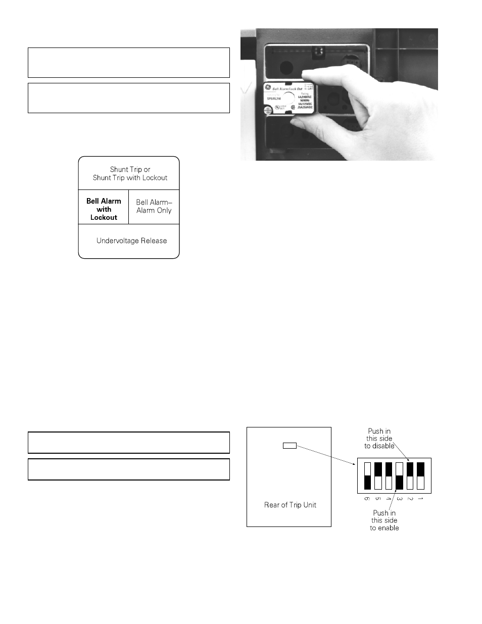
Figure 5. Accessory switch on the rear of a MicroVersaTrip Plus™ or
MicroVersaTrip PM™ Trip Unit, showing the factory settings (solid
part indicates that switch is pushed in on that side).