Data sheet, Surface mount information – GE Industrial Solutions EHHD020A0F Hammerhead Series User Manual
Page 12
GE
Data Sheet
EHHD020A0F Hammerhead™ Series; DC-DC Converter Power Modules
18-75Vdc Input; 3.3Vdc, 20.0A, 66W Output
April 4, 2013
©2012 General Electric Company. All rights reserved.
Page 12
Surface Mount Information
(continued)
Tin Lead Soldering
The EHHD020A0F power modules are lead free modules and
can be soldered either in a lead-free solder process or in a
conventional Tin/Lead (Sn/Pb) process. It is recommended
that the customer review data sheets in order to customize
the solder reflow profile for each application board
assembly. The following instructions must be observed
when soldering these units. Failure to observe these
instructions may result in the failure of or cause damage to
the modules, and can adversely affect long-term reliability.
In a conventional Tin/Lead (Sn/Pb) solder process peak
reflow temperatures are limited to less than 235
o
C.
Typically, the eutectic solder melts at 183
o
C, wets the land,
and subsequently wicks the device connection. Sufficient
time must be allowed to fuse the plating on the connection
to ensure a reliable
solder joint. There are several types of SMT reflow
technologies currently used in the industry. These surface
mount power modules can be reliably
soldered using
natural forced convection, IR (radiant infrared), or a
combination of convection/IR. For reliable soldering the
solder reflow profile should be established by accurately
measuring the modules CP connector temperatures.
Lead Free Soldering
The –Z version of the EHHD020A0F modules are lead-free
(Pb-free) and RoHS compliant and are both forward and
backward compatible in a Pb-free and a SnPb soldering
process. Failure to observe the instructions below may
result in the failure of or cause damage to the modules and
can adversely affect long-term reliability.
REFL
O
W
TE
MP
(
C)
REFLOW TIME (S)
Figure 26. Reflow Profile for Tin/Lead (Sn/Pb)
process.
MAX TEM
P
SO
LD
ER (
C)
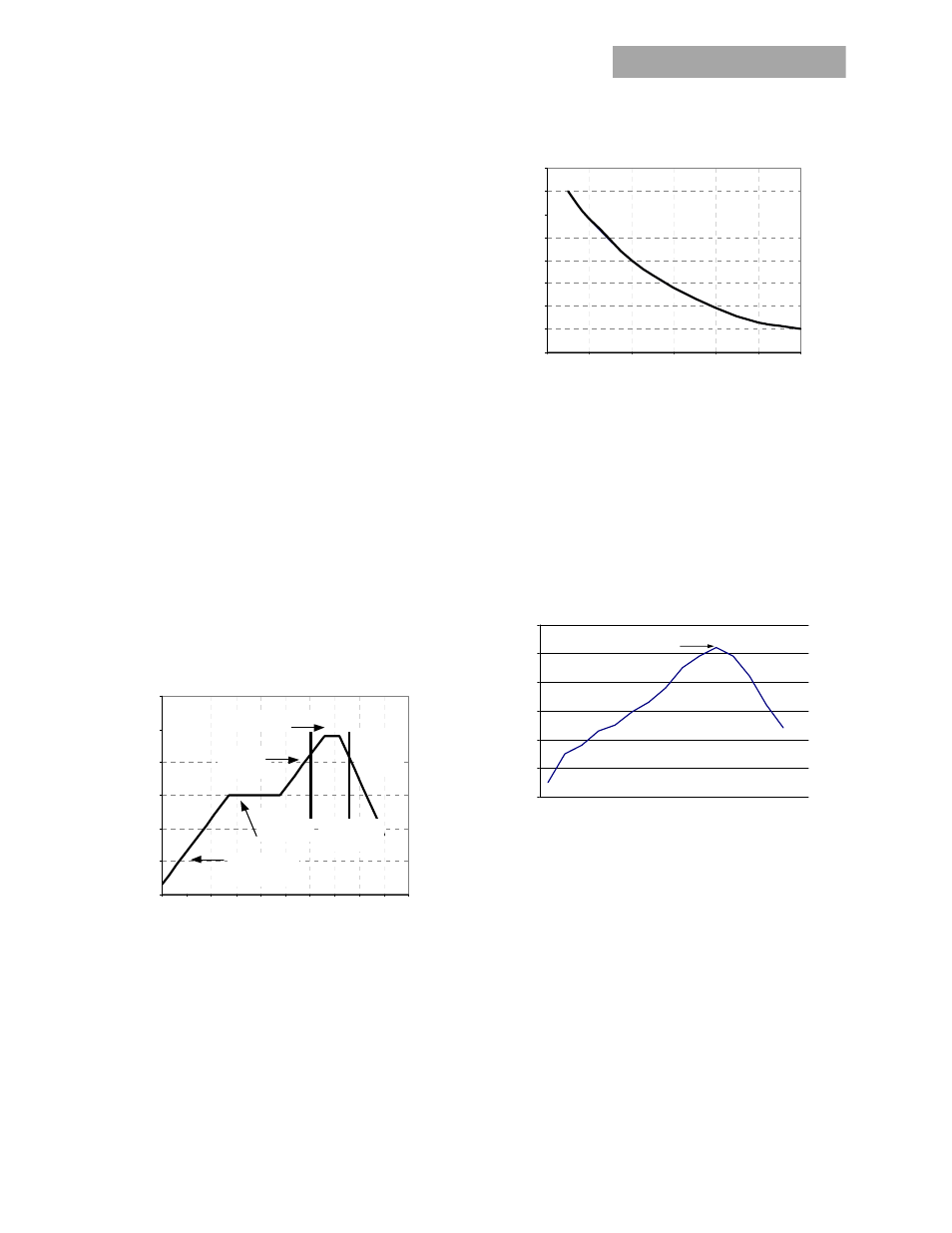
Figure 27. Time Limit Curve Above 205
o
C for Tin/Lead
(Sn/Pb) process.
Pb-free Reflow Profile
Power Systems will comply with J-STD-015 Rev. C
(Moisture/Reflow Sensitivity Classification for Nonhermetic
Solid State Surface Mount Devices) for both Pb-free solder
profiles and MSL classification procedures. This standard
provides a recommended forced-air-convection reflow
profile based on the volume and thickness of the package
(table 4-2). The suggested Pb-free solder paste is Sn/Ag/Cu
(SAC). The recommended linear reflow profile using
Sn/Ag/Cu solder is shown in Figure 25.
Figure 28. Recommended linear reflow profile using
Sn/Ag/Cu solder.
Post Solder Cleaning and Drying Considerations
Post solder cleaning is usually the final circuit-board
assembly process prior to electrical board testing. The result
of inadequate cleaning and drying can affect both the
reliability of a power module and the testability of the
finished circuit-board assembly. For guidance on
appropriate soldering, cleaning and drying procedures, refer
to GE Board
Mounted Power Modules: Soldering and Cleaning Application
Note (AN04-001).
0
50
100
150
200
250
300
P reheat zo ne
max 4
o
Cs
-1
Soak zone
30-240s
Heat zo ne
max 4
o
Cs
-1
P eak Temp 235
o
C
Co oling
zone
1-4
o
Cs
-1
T
lim
above
205
o
C
200
205
210
215
220
225
230
235
240
0
10
20
30
40
50
60
Pe r J-STD-020 Rev. C
0
50
100
150
200
250
300
Reflow Time (Seconds)
Re
fl
o
w
T
em
p
(
°C)
Heating Zone
1°C/Second
Peak Temp 260°C
* Min. Time Above 235°C
15 Se conds
*Time Above 217°C
60 Seconds
Cooling
Zone