Step 1 – unpack and inspect, Step 2 – breaker status, Step 3 – installation – GE Industrial Solutions Record Plus Shunt Trip and Undervoltage Release User Manual
Page 2
Voltage Shunt
Trip
UVR
Vac
Vdc
Cat. No.
Rating, mA
Cat. No.
Rating, mA
— 12
FASHTB
200 — —
24 24
FASHTD
150
FAUVRD 50
48 48
FASHTF 60 FAUVRF 20
110–130 110–125 FASHTJ
40
FAUVRJ
15
120 —
FASHTK 40
—
—
220–240
250
FASHTN 20 FAUVRN 15
277 —
FASHT7 11 FAUVR7 15
400–480
— FASHTU 20 FAUVRU 15
50 or 60 Hz.
Shunt trip suitable for use with ground-fault sensing and relaying equipment;
55% trip.
Table 1. Catalog numbers and ratings for Record Plus™ shunt trip and undervoltage release accessories.
Step 1 – Unpack and Inspect
Unpack the shunt trip or undervoltage release kit and
inspect it for shipping damage. Read the circuit breaker
installation instructions carefully. Insure that the circuit
breaker and the accessory have the proper ratings for
current, voltage, interruption, and contact duty; wire
routing; installation; and operation for the application.
Accessories with the catalog number suffix W are factory
equipped with #18 AWG wire leads, 36 inches long.
Shunt trip leads are black and undervoltage release
leads are blue.
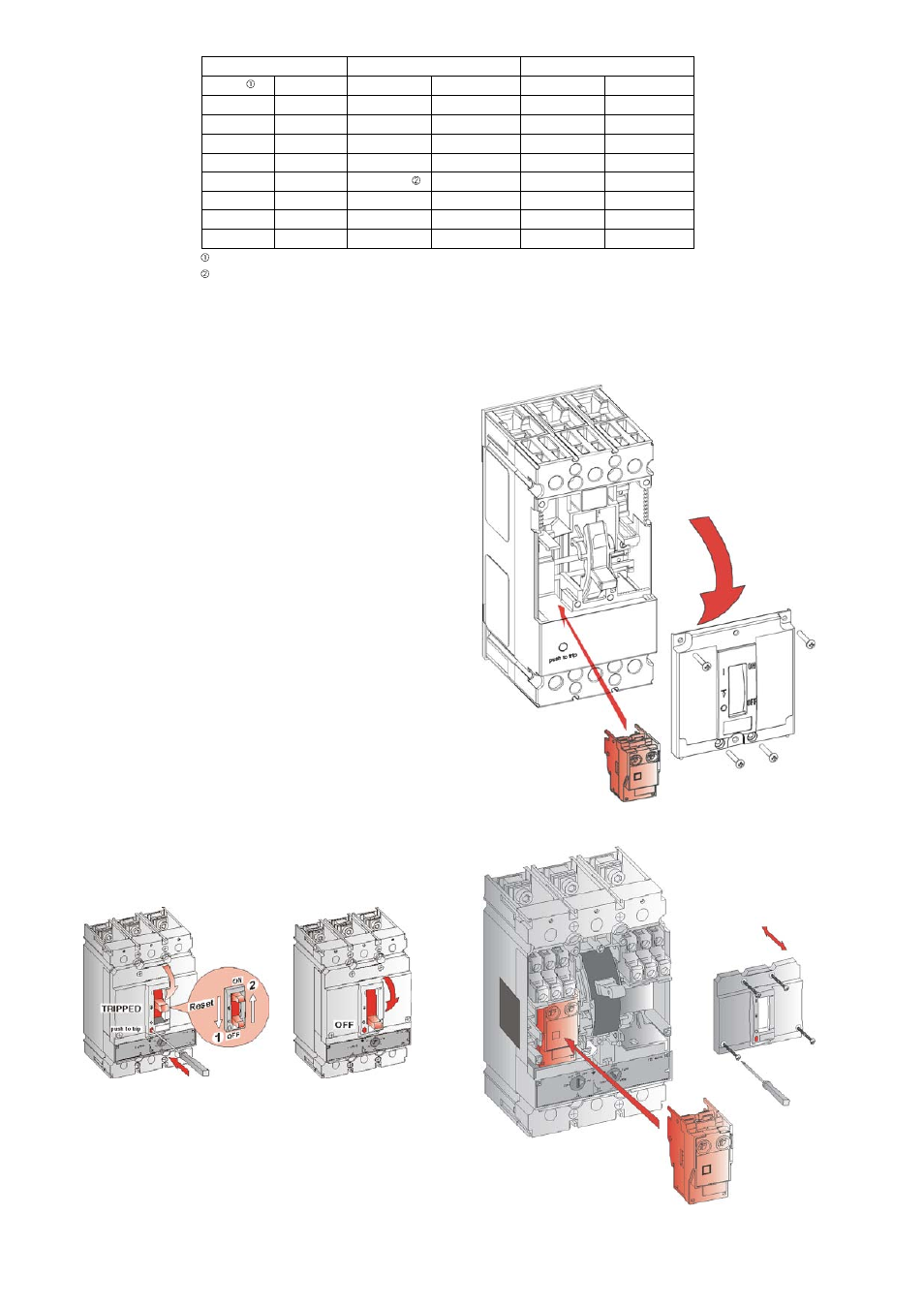
Step 2 – Breaker Status
Either trip the circuit breaker by activating the red trip
button on the front of the breaker or move the breaker
handle to the
OFF
position, both shown in Figure 2.
Step 3 – Installation
1. Loosen, but do not remove, the captive screws
holding the accessory cover on the circuit breaker,
as shown in Figure 3 for an FB100 and FC100
breaker and in Figure 4 for an FE150 or FE250
breaker Figure 5 for an FG400/FG600 Breaker.
Remove the cover.
2. The shunt trip or undervoltage release snaps into
place in its designated pocket in the circuit
breaker, as illustrated in Figure 3, Figure 4 and
Figure 5. It can be easily removed by gently
prying from underneath with a small screwdriver.
Figure 2. (a) Tripping the breaker or (b) turning it OFF.
Figure 3. Installation in an FB100 and FC100 circuit breaker.
(a)
(b)
Figure 4. Installation in an FE150 or FE250 circuit breaker.