Product description, Step 1 – unpack and inspect, Step 2 – installation – GE Industrial Solutions Record Plus TDR, NEMA 1, 12: FE250 User Manual
Page 2: Step 3, Handle operation
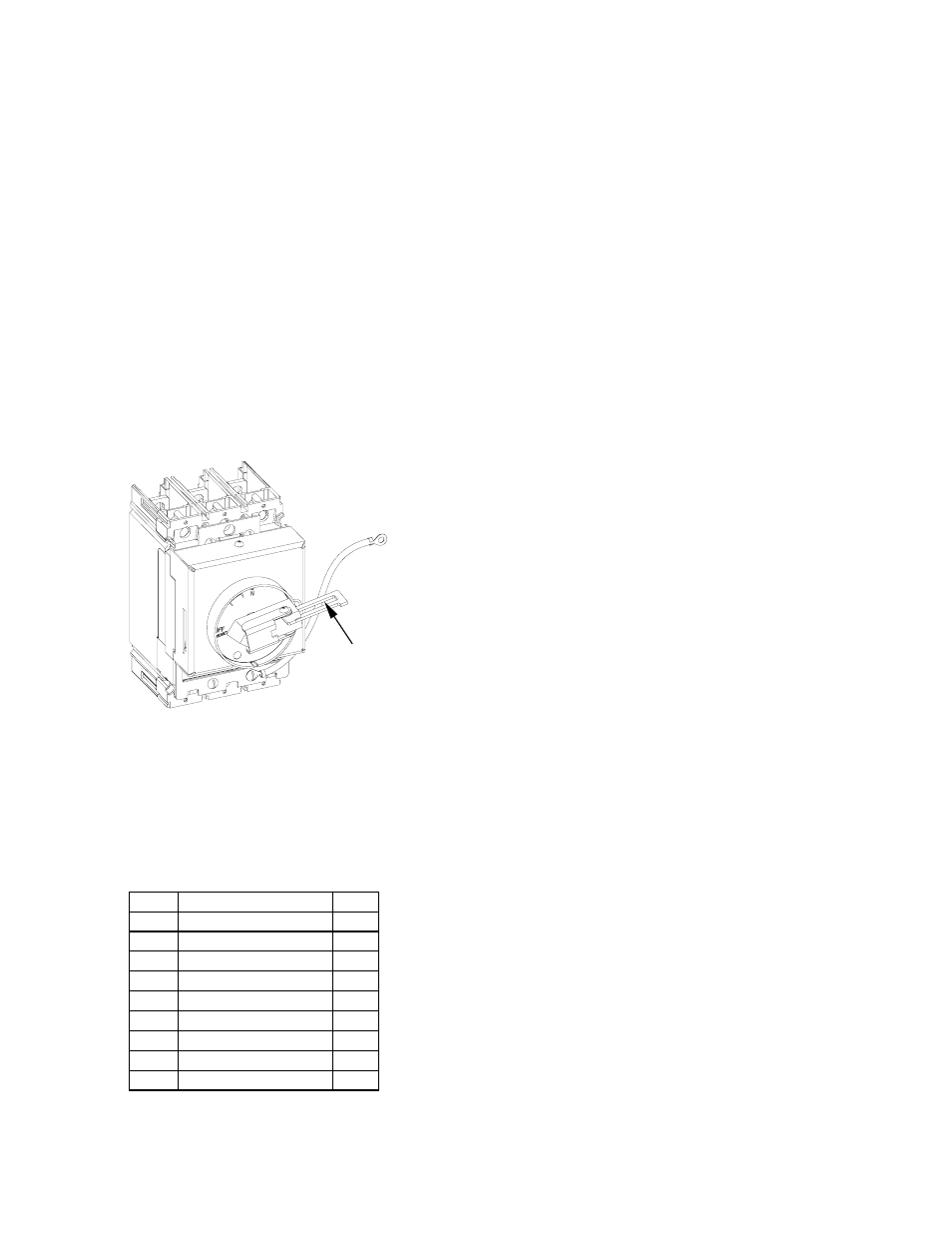
Product Description
These instructions describe the installation
procedure for the integral handle operator accessory,
type TDR, on
Record Plus™
FE250 circuit breakers,
as illustrated in Figure 1.
The type TDR handle is designed for direct
mounting to the breaker in either vertical (cat. no.
FENRC and FENRCI) or horizontal orientation (cat.
no. FENRD). A door ring on the handle operator
projects through a hole in the front of the enclosure
door. These handles are suitable for use with NEMA
1, NEMA 12 enclosures.
An interlock kit (cat. no. SEFRDRCK) for adapting
the enclosure door and the door ring gasket (cat. no.
SEFRGSK) are available separately for FENRCI and
FENRD.
DEH41028
Step 1 – Unpack and Inspect
Unpack the integral handle operator kit and inspect
the parts for any shipping damage. Verify that all
parts are supplied, as listed in Table 1.
Note that the numbers in brackets in the following
Figures and installation instructions refer to the item
numbers in Table 1.
Item Description
Qty.
1 Operator
assembly 1
2 7/16”
spacer
2
3 L
bracket
1
4 Lock
washer
4
5 #10-32x3-3/4”
screw 2
6 Grounding
cable
1
7 41/64”
spacer
2
8 #10-32x4”screws
2
9 SEMs
screw
1
Table 1. Parts supplied in the type
TDR integral handle operator kit.
Step 2 – Installation
Use the following procedure to install the handle
operator kit to the circuit breaker. Outline drawings
showing the dimensions of the installed operator are
found in Figure 7.
1.
Push the trip button to place the breaker
operating handle in the TRIP position, as
illustrated in Figure 3
2.
Mount the breaker to the enclosure with two
7/16”spacer [2], one L-bracket [3], two lock
washers [4] and two #10-32 x 3-3/4" screws [5],
as shown in Figure4. Tighten the screws to 27 -
32 in-lb.
3.
Turn the rotary handle in the handle operator
assembly [1] to the TRIP position. Mount the
operator assembly to the breaker with a
grounding cable [6], two 41/64” spacers [7], two
#10-32
x
4" screws [8] and two lock washers [4],
as shown in Figure5. Tighten the screws to 27 -
32 in-lb.
Figure 2. Locking the circuit breaker OFF.
Padlock
Slot
4.
Secure the handle operator assembly [1] to the
L bracket [3] with the SEMS screw [9], as shown
in Figure 6.
Use the identical procedure to install the horizontal-
mount rotary handle, as shown in Figure 10
.
Step 3
-
Handle Operation
Complete the installation of the circuit breaker
according to installation instructions DEH40360.
The mechanism operates with a rotary motion from
the OFF/RESET position to ON.
In FENRCI/D, when the breaker is ON, the
interlock arm prevents the enclosure door from
opening. If it is necessary to open the door with the
breaker ON, turn the interlock defeat screw
clockwise to disengage the interlock arm.
To lock the handle in the OFF position, pull the
hasp out of the end of the handle and through the
slot in the door ring, as shown in Figure 2. Insert a
padlock through the slot in the hasp to prevent the
handle from rotating. The locking hasp accepts up
to three padlocks with 1/4-inch shanks.