GE Industrial Solutions Record Plus TDR Door-Ring Interlock Kit: FC100 User Manual
Page 3
[2]
[1]
Door
[5]
Figure 4. Secure door rings with pan head screws.
e. Adjust for proper alignment of indication plate
and hole in the door.
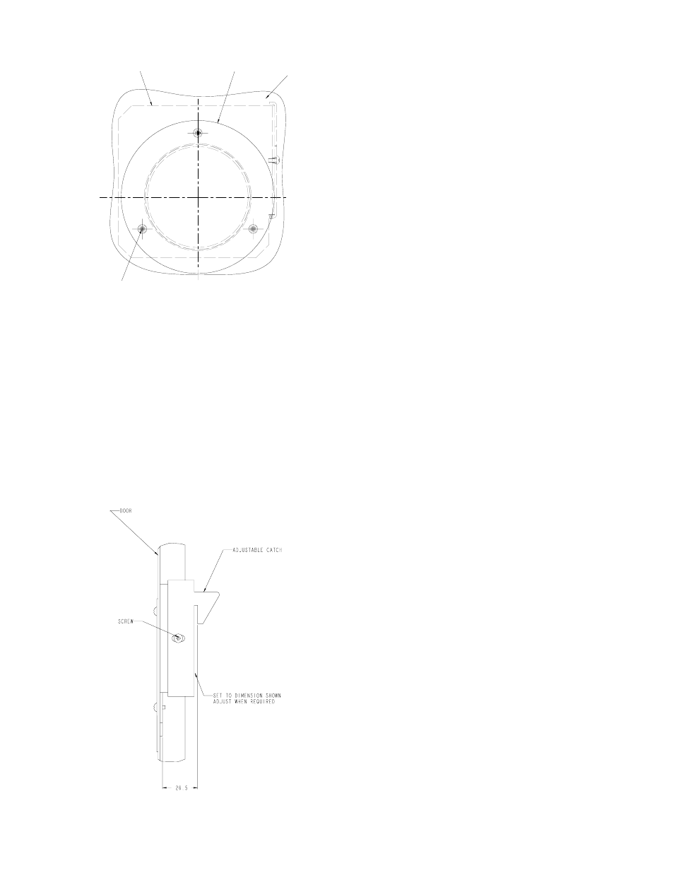
1) Adjust catch height per Figure 5.
2) Turn integral handle to OFF position.
3) Close enclosure door.
4) Adjust external ring on the door so it is
concentric with handle ring.
5) Small notch at right hand side of exterior
ring must be immediately adjacent to the hole
horizontal centerline.
6) Tighten pan head screws [5].
Figure 5. TDR integral handle operator catch kit.
B. Adjust sliding interlock catch for circuit breaker per
Figure 5 and tighten with furnished screw.
C. Check operation of interlocking features.
1. Close enclosure door. Turn handle to ON. Door
should not be able to open with handle in ON position.
To open door, turn defeater screw (see figure 1) located
in indicator plate counterclockwise, or turn handle to OFF
position.
2. Open enclosure door. Open door should prevent
turning disconnect ON without first defeating interlock.
The interlock arm must be pushed toward the mounting
surface and held while turning the handle to ON.
D. Install optional gasket (SEFRGSK) to the interior door
ring [1], facing the pan of the integral handle. Consult
the GE BuyLog© for gasket kit ordering details.
[3]
[5]