Step 1 – unpack and inspect, Step 2 – mount protective device, Step 4 – secure door ring interlock catch kit – GE Industrial Solutions Record Plus TDR Door-Ring Interlock Kit: FC100 User Manual
Page 2
the figures refer to the item numbers in Table 1.
Item Description
Qty.
1 Interior
ring
1
2 Exterior
ring
1
3 Interlock
catch
1
4 Lockwasher
1
5 #8-32
screws
4
Table 1. List of parts in theTDR integral handle operator catch kit.
Step 1 – Unpack and Inspect
Unpack the integral handle operator kit and inspect the
parts for any shipping damage. Verify that all parts are
supplied, as listed in Error! Reference source not found..
Step 2 – Mount protective device
Locate and mount the breaker within the enclosure per
installation instructions DEH40463 for the FC100 circuit
breaker. The distance from the vertical centerline of the
protective device to the enclosure wall (with hinges) has a
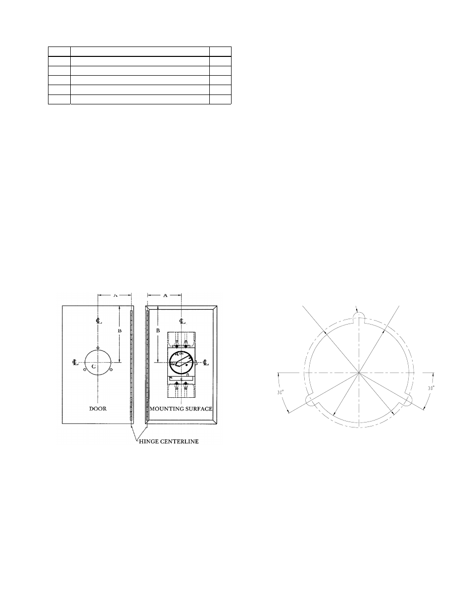
minimum distance A, illustrated in Figure 2. Distance A
must be equal to or greater than one-half the length of the
enclosure door from the hinged side to the latch side.
Preferably, the hole should be located toward the latch
side for interlock leverage.
Figure 2. TDR integral handle operator catch kit.
Step 3 – Secure integral handle
operator to protective device
Mount integral handle mechanism to circuit breaker after
the breaker is secured to the enclosure according to
installation instructions DEH40914 for the FCNRC or
FCNRD TDR handle operator.
Step 4 – Secure door ring
interlock catch kit
Each kit consists of an exterior ring, interior ring,
interlock catch, and mounting hardware. The kit is
designed to assure proper door ring alignment and
interlocking. The interlock catch for the protective
device
must be secured to the interior ring with one of the #8-32
screws furnished.
A. Locate the center of a circle for the integral handle
indication ring on the enclosure door, referring to Figure
2 and the following steps.
1. Obtain distances A and B.
a. The horizontal distance from the centerline of
the indication ring centerline of the enclosure.
b. The vertical distance from the centerline of the
indication ring to the top of the enclosure.
2. Assuming the mounting surface of the enclosure
and the closed door to be parallel, transcribe
dimensions A and B to the enclosure door per figure 2.
a. Using point C as your center, scribe a circle,
diameter is 3.437” (87.3mm).
b. Cut out the circle in the enclosure door.
c. Drill three 0.406“ (10.3mm) diameter holes in
the enclosure door about a 3.812” (96.82mm)
diameter per Figure 3.
∅0.406”
∅3.437”
∅3.812”
Figure 3. Hole cutout and drill pattern.
d. Loosely secure each ring to the door with pan
head screws per Figure 4.