Description, Electrical operation, Automatic reset – GE Industrial Solutions Record Plus Motor Operator Mechanism: FC100 User Manual
Page 3: Manual operation, Figure 5. alignment of mounting brackets, Step 3 – operation description
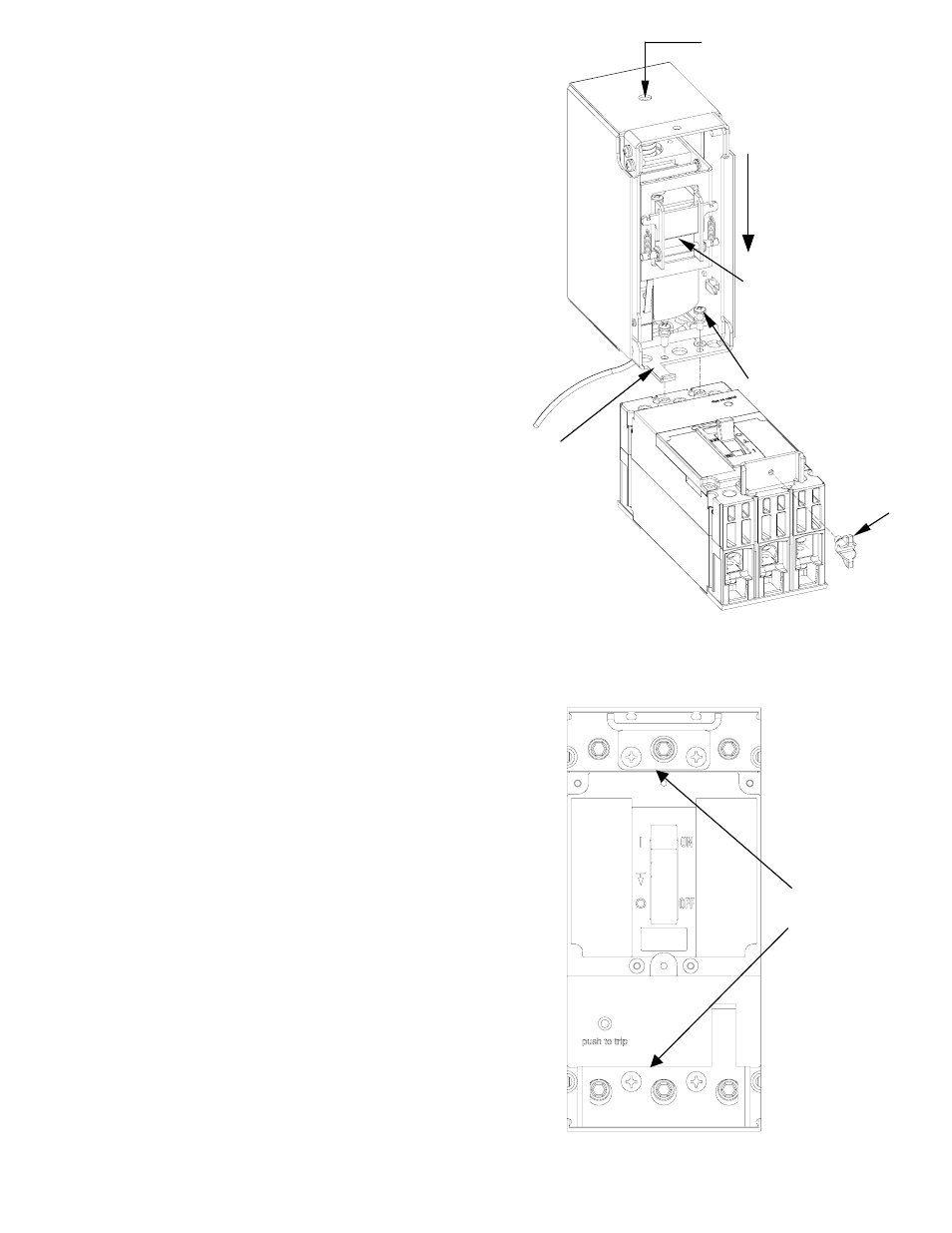
4. Align the Mounting brackets parallel to each
other as shown in Figure 5.
5.
Align the breaker handle with the operator
mechanism, by adjusting the mechanism
position with the screw as shown in Figure 4
Close the operator and fasten the wing
screw [7]
Step 3 – Operation
Description
A motor Operated mechanism is designed to
open, close, and reset a circuit breaker by remote
control.
In an operating installation, the customer must
supply normally open ON and OFF push –
buttons, external wiring, a control power source
and any control circuitry.
Electrical Operation
With the breaker and operating mechanism in
their OFF positions, press ON button to energize
the motor, closing the breaker. When the breaker
handle reaches the ON position, an internal limit
switch disconnects the control circuitry.
When the OFF button is pressed, the motor is
energized, opening the breaker. After the breaker
handle reaches the OFF position, a limit switch de-
energizes the control circuit.
When the circuit breaker trips automatically, there
is no external trip indication, unless a separate bell
alarm accessory is provided to actuate a warning
device. It is necessary to press OFF to reset the
breaker.
Automatic Reset
For automatic reset, an auxiliary switch, available
as an accessory, returns the breaker to the
OFF/RESET position after it has tripped. The
switch is mounted inside the breaker and wired in
parallel with the OFF button. When the breaker
trips, the switch closes, moving the breaker handle
to OFF/RESET position. After the motor-operated
mechanism has reset the breaker, the limit switch
again opens the circuit. To use automatic reset,
the ON push – button must be SPDT type and
wired as in Figure 7. (The Auto/ Reset scheme
applies to AC devices only and is not applicable to
DC applications).
Manual Operation
Unscrew the wing nut and lift the operator to
disengage the handle and operate the breaker
handle. To return to electrical operation, align
the breaker handle with the operator mechanism
and close the operator and fasten the wing screw.
Figure 6 is the outline view of completed
installations with dimensions.
ACCESS TO SCREW, FOR
MECHANISM ADJUSTMENT
‘OFF’ SIDE
ALIGN BREAKER
HANDLE TO THIS
AREA
[4,5,8]
MOUNTING
BRACKET
[7]
Figure 4. Mounting of Motor Operating Mechanism on
Breaker
PARALLEL
ALIGNMENT
Figure 5. Alignment of mounting brackets