Product description, Step 1 – unpack and inspect – GE Industrial Solutions Record Plus Motor Operator Mechanism: FC100 User Manual
Page 2
Product Description
These instructions describe the installation
procedures for the Motor Operator Mechanism
accessory on
Record Plus™
circuit breakers, as
illustrated in Figure 1.
The complete kits are available in the catalog
numbers mentioned in Table 1.
The kit is common to all the catalogs, providing
the necessary parts for mounting the motor
operator mechanism on the breaker as shown in
Figure 2.
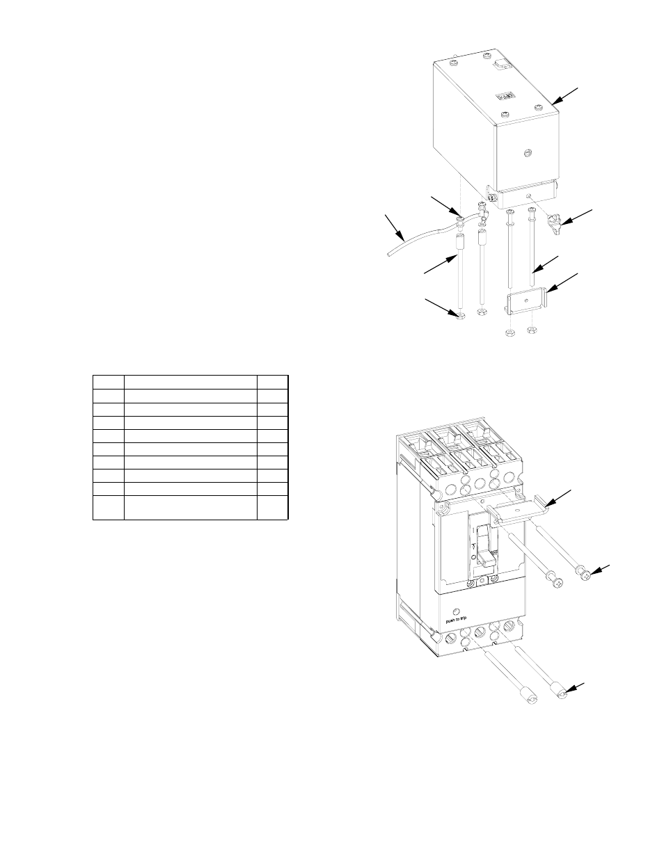
Step 1 – Unpack and Inspect
Unpack the Motor operating mechanism kit and
inspect the parts for any shipping damage. Verify
that all parts are supplied, as listed in Table 2. The
parts are illustrated in Figure 2.
Note that the numbers in brackets in the following
figures and installation instructions refer to the
item numbers in Table 2.
Item Description
Qty.
1 Top
Bolting
Plate
1
2 Mounting
Screw
2
3
Screw, #8-32 x 3.50"
2
4
Screw, #8-32 x 0.375"
2
5 Lock
Washer
4
6
Nut, Hex #8-32
4
7 Wing
Screw
#10-24
1
8 Grounding
Wire
1
9 Motor
Operator
Mechanism
1
Table 2. List of parts included in the Motor operator
Mechanism kit.
Step 2 – Install the Breaker and
Motor Operating Mechanism
1.
Move the breaker handle to the OFF position.
2.
Mount the breaker with mounting screws[2],
# 8-32 x 3.50" screws [3] and Top bolting
plate[1], as illustrated in Figure 3. Tighten the
screws to 16 - 20 in-lb.
Complete the installation
of the circuit breaker according to installation
instructions DEH40463.
3.
Position the Mounting bracket of motor
operator assembly on the breaker, as illustrated
in Figure 4. Insert two #8-32 x 0.375" screws
[4] through the mounting holes in the
mounting bracket and into the heads of the
breaker mounting screws [1], with the
grounding wire [8] attached to one of the
screws. Tighten the screws to 16 - 20 in-lb.
Secure the other end of the grounding wire to a
suitable ground location.
[9]
[4,5]
[8]
[7]
Figure 2. Parts supplied in the Motor operator kits.
Figure 3. Mounting the breaker.
[1]
[2]
[3,5]
[1]
[2]
[3]
[6]