4 thermal considerations – OSRAM PrevaLED Core Z3 User Manual
Page 14
14
PrevaLED
®
Core Z3 LED modules
|
Thermal considerations
Defi ne boundary
conditions
Estimate heat sink
thermal resistance on
LED module level
Select heat sink
thermal resistance
Total power dissipation of the
LED module, max. ambient
temperature t
a
, max. reference
temperature t
r
according to life-
time requirements
Use the estimated R
th
as a tar-
get for a possible heat sink
profi le and examine the perfor-
mance curve in the heat sink
manufacturer’s catalog.
R
th
=
t
r
- t
a
P
th
t
r
measured at the t
c
point
4 Thermal considerations
The proper thermal design of an LED luminaire is critical for
achieving the best performance and ensuring the longest
lifetime of all components. Due to the high effi cacy of Pre-
vaLED
®
Core Z3 LED modules, only a partial amount of the
introduced electrical power has to be dissipated through the
back of the LED module. The thermal power that has to be
dissipated for PrevaLED
®
Core Z3 LED modules is given
below.
4.1 Thermal power values
4.2 TIM and other accessories
When mounting a PrevaLED
®
Core Z3 LED module within a
luminaire, it is recommended to use thermal interface
material (TIM) between the back of the LED module and the
luminaire housing or heat sink. It is recommended to use
thermal paste, but thermal foil can also be used. In order to
balance possible unevenness, the material should be
applied as thinly as possible, but as thickly as necessary.
In this way, air inclusions, which may otherwise occur, are
replaced by TIM and the required heat conduction between
the back of the LED module and the contact surfaces of the
luminaire housing is achieved. For this purpose, the planarity
and smoothness of the surface should be optimized.
The list below is a selection of suppliers of thermal interface
materials. Additional suppliers for thermal management
support can also be found via OSRAM’s LED Light for your
network:
www.ledlightforyou.com
.
4.3 Cooling system and heat sinks
For the selection of a suitable heat sink, several points
regarding thermal resistance have to be considered.
The selection is usually done through the following
necessary steps.
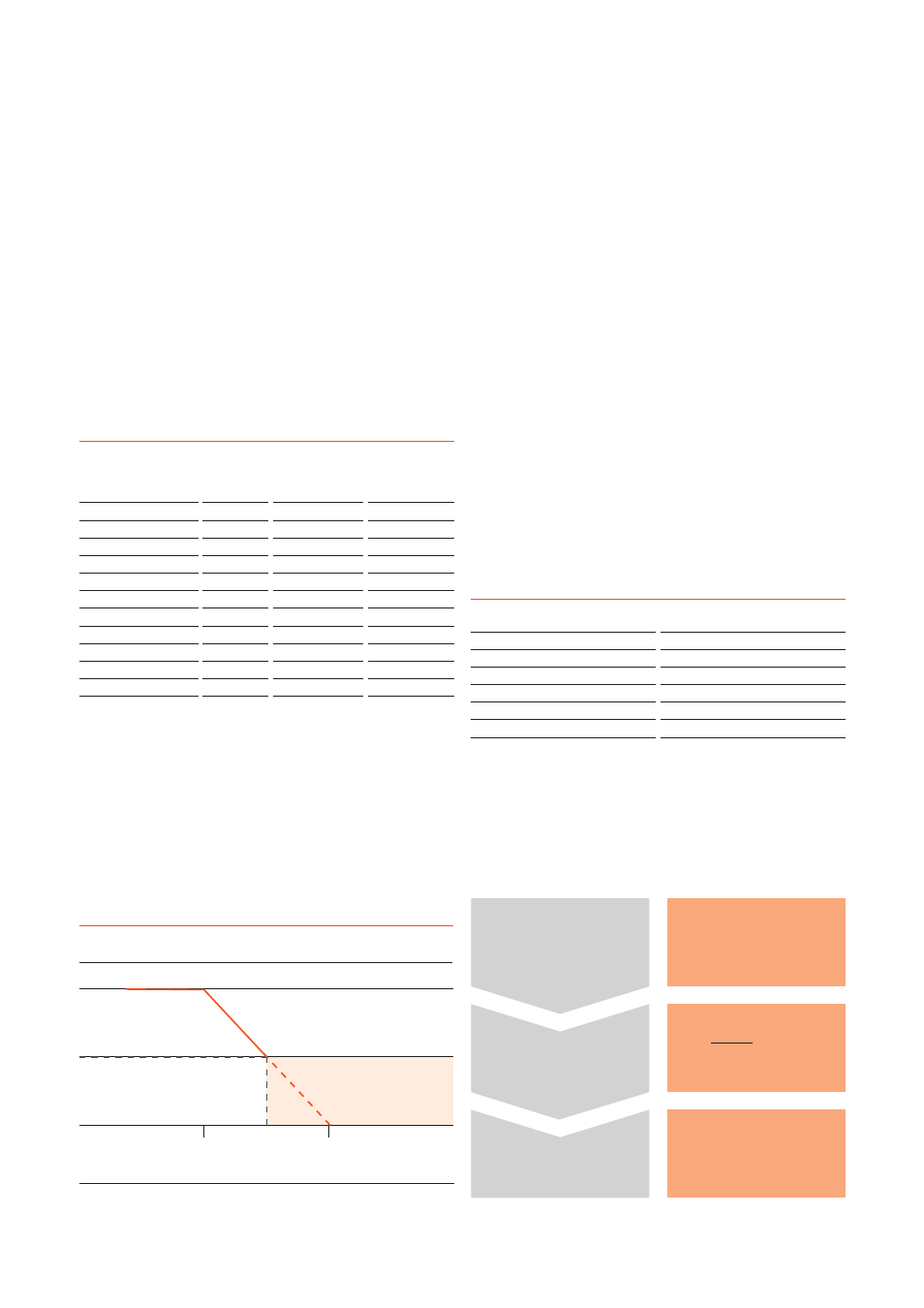
To achieve the best possible lifetime of the module and to
save it from damage by overheating, a thermal protection
feature is added. This feature is only usable when operating
the module with an OSRAM OTi control gear.
The characteristics of the thermal protection are shown in
the following diagram:
Product
Typ. thermal
power [W]
1)
Max. thermal
power [W] at
nominal current
1)
Max. allowable
thermal resis-
tance R
th
[K/W]
2)
PL-CORE-1100-830-Z3
7.7
8.2
4.91
PL-CORE-1100-840-Z3
6.9
7.3
5.48
PL-CORE-2000-830-Z3
11.2
12.4
3.23
PL-CORE-2000-930-Z3
14.4
15.6
2.56
PL-CORE-2000-840-Z3
10.1
11.0
3.63
PL-CORE-3000-830-Z3
15.9
17.4
2.30
PL-CORE-3000-930-Z3
21.2
23.3
1.72
PL-CORE-3000-840-Z3
15.1
16.6
2.41
PL-CORE-5000-830-Z3
28.6
31.3
1.28
PL-CORE-5000-930-Z3
33.7
36.8
1.09
PL-CORE-5000-840-Z3
25.1
27.4
1.46
Thermal interface materials
Alfatec
www.alfatec.de
Kerafol
www.kerafol.de
Laird
www.lairdtech.com
Bergquist
www.bergquistcompany.com
Arctic Silver
www.arcticsilver.com
Wakefield
www.wakefield.com
1) Value measured at the t
c
point at a reference temperature (t
r
) of 65 °C.
2) Value measured at the rear of the luminaire at an ambient temperature
of 25 °C.
Selection of a heat sink
The behaviour below 50 % of the system current depends on the
nominal system current and the applied ECG.
t
c
[°C]
75
105
Current [% of minimal ECG current]
0
100
50