OSRAM PrevaLED Core Z3 User Manual
Page 13
13
PrevaLED
®
Core Z3 LED modules
|
Electrical considerations
3.8 Maximum allowed number of control gears
per circuit breaker
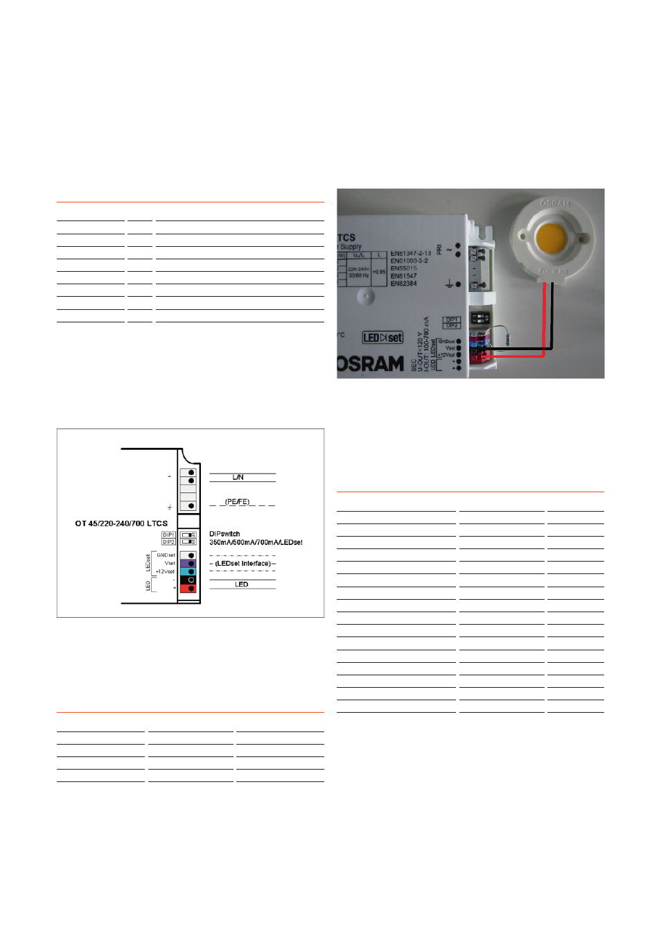
The resistor has to be placed between Vset and GNDset:
DIP1
DIP2
Current
Off
Off
LEDset
Off
On
700 mA
On
Off
500 mA
On
On
350 mA
Please note:
To activate the LEDset interface, both DIP switches of the
LED module have to be in the “OFF” position.
For further information on the LEDset interface, please refer
to the LEDset application note at
www.osram.com
.
Example of wiring:
B16
B10
OTe 35/700
50
30
OT 35/LCTS
84
52
OT 45 LCTS
60
40
OT 45 DALI LCTS
47
18
OTe 25/CS
50
30
OTe 35/CS S
44
28
OTe 35/CS
25
15
OTe 50/1A4 CS
25
15
OTe 50/1A0 CS
25
15
OTe 50/CS FAN
25
15
OT FIT 15CS
28
17
OT FIT 25/CS
28
17
OT FIT 35/CS
28
17
OTi DALI 25
84*
52*
OTi DALI 35
60*
40*
OTi DALI 50 FAN
13
18
3.9 ESD
It is not necessary to handle PrevaLED
®
Core Z3 LED
modules in electrostatic protected areas (EPAs). To protect
a PrevaLED
®
Core LED module from electrostatic damage,
do not open it. The LED module fulfi lls the requirement of
the immunity standard IEC/EN 61547.
* Preliminary data
The following values result for the modules which are
possible to drive with LCTS drivers:
Module
I [mA] R [Ohm]
PL-CORE-2000-830 400
22419
PL-CORE-2000-840 385
21715
PL-CORE-2000-930 490
26642
PL-CORE-3000-830 590
31335
PL-CORE-3000-840 575
30631
PL-CORE-3000-930 730
Use DIP switch for 700 mA. Module is under-driven.
PL-CORE-5000-830 950
Use DIP switch for 700 mA. Module is under-driven.
PL-CORE-5000-840 885
Use DIP switch for 700 mA. Module is under-driven.