OSRAM HALOTRONIC-PROFESSIONAL HTL User Manual
Page 14
3
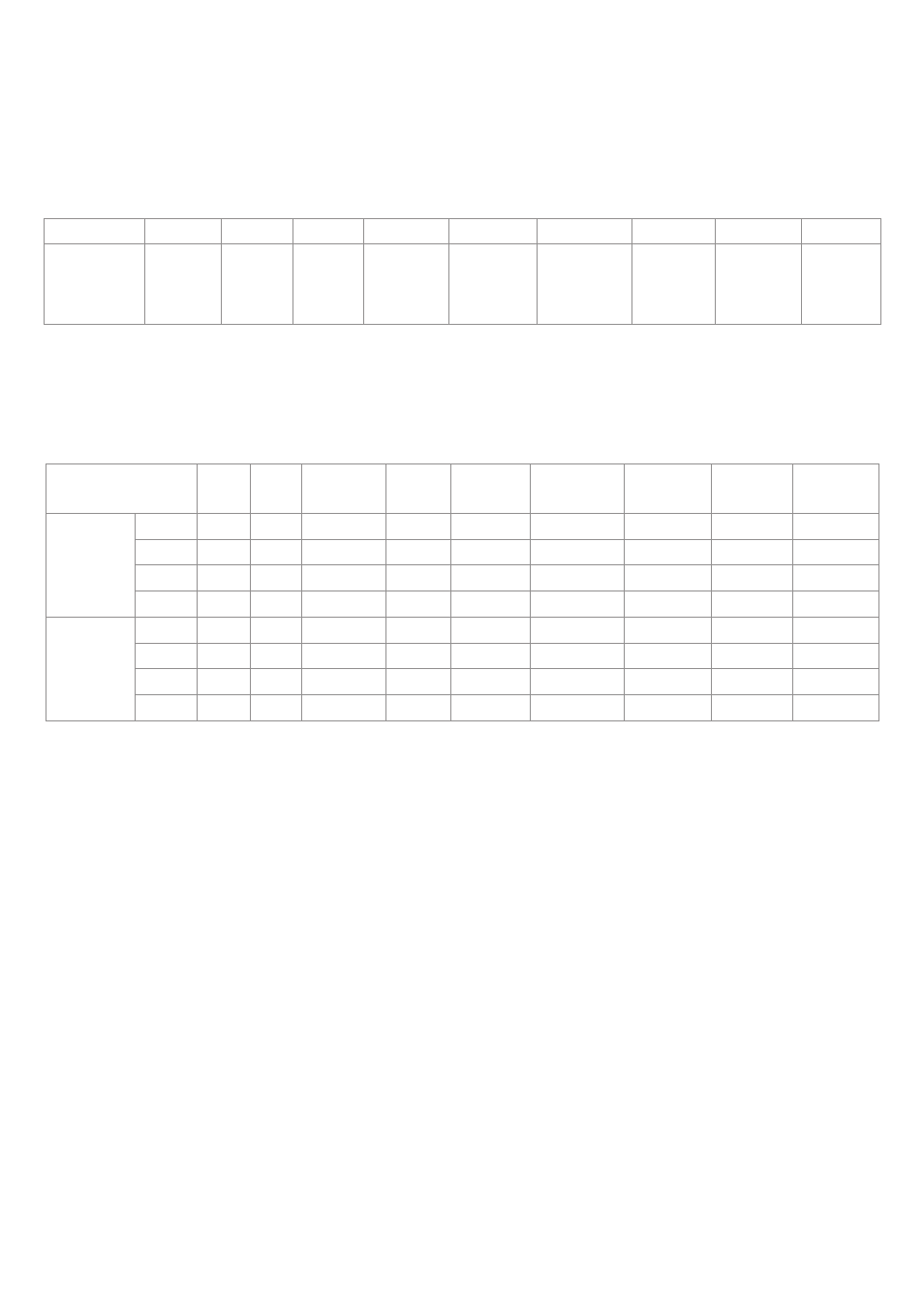
3.15 Start-up current
The table 3 shows the peak values for the maximum start-up current
Î
max
(time: 0 ms, half sine wave) for a cold lamp.
Table 3
3.16 Automatic circuit-
The following table indicates the maximum number of HALOTRONIC
®
brakes
transformers that can be connected to automatic circuit braker:
Table 4
3.17 Service life
The failure rate of electronic components obviously depends on their
specifications and construction quality but the temperature at which
they operate also plays quite a significant role. HALOTRONIC
®
units
are designed so that at the maximum permissible device temperature
(tc max.) a failure rate of fewer than 2 per thousand per 000 hours of
operation can be expected. This corresponds to a life of 50,000 hours
at a percentage component failure of less than 0 % (HTM and HTN:
30,000 hours at a percentage component failure of less than 0 %).
By lowering the operating temperature by 0 degrees celcius it is ne-
arly possible to double the lifetime.
HTM 70 HT 70 L HTN 75 HTM 105 HT 105 L HT 120 LF HTM 150 HT 150 L HT 210 L
Einschalt-
strom
Î
max
[A]
0,6
0,7
0,6
0,7
2,4
2,4
2,0
3,5
7,4
Leitungschutz-
schalter
HTM
70
HT
70L
HTN
75 I u. S
HTM
105
HT
105L
HT
120LF
HTM
150
HT
150L
HT
210L
Auslöse-
charak-
teristik B
B0
37
37
33
23
9
6
6
0
4
00
7
B6
59
59
53
38
3
2
26
0
22
0
B20
74
74
66
47
39
27
33
0
28
0
4
B25
92
92
83
59
49
34
42
0
35
0
7
Auslöse-
charak-
teristik C
C0
37
37
33
23
23
20
6
0
6
0
C6
59
59
53
38
37
32
26
0
26
0
8
C20
74
74
66
47
47
40
33
0
33
0
23
C25
92
92
83
59
58
50
42
0
4
0
29