9when installing halotronic – OSRAM HALOTRONIC-PROFESSIONAL HTL User Manual
Page 10
9
When installing HALOTRONIC
®
outside a luminaire, make sure that it
is not placed too near a heat source (such as the lamp itself), other-
wise overheating may occur.
When installing HALOTRONIC
®
inside a luminaire, the measuring point
temperature on the casing (tc) is the crucial factor.
If units without a casing are installed in a luminaire, temperature tc
must be measured on certain electronic components. The limit tem-
peratures on the components specified for the particular model must
not be exceeded. (see Fig. 6).
HT 50/230-240/12 SB
t
c
= 00 °C
Fig. 6
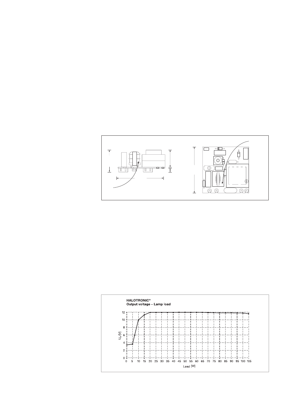
3.5. Minimum load
HALOTRONIC
®
transformers must be operated with a lamp wattage
which corresponds at least to the minimum load (see technical data).
If this minimum load is not reached, harmonics and/or radio inter-
ference values may exceed the permissible thresholds and output
voltage will fall considerably (see Fig. 7). The unit is unlikely to be da-
maged, however. Fig. 7 shows the output voltage curve as a function
of lamp load for HT 05/230/2 L.
HALOTRONIC
®
HT 105/230/12 L
Output voltage – Lamp load
Ue = 230 V ~
Load line: 15 cm
Fig. 7
28,5 mm
53 mm
t
c
22 mm
1,5 mm
5 mm
C1
PRI
C5
L1
C2
R1
HK2
R12
L2
D7
C4
D2
D3
C5
L3
L4
SEC
FUSI
0,27R
53 mm
t
c
28,5 mm
53 mm
t
c
22 mm
1,5 mm
5 mm
C1
PRI
C5
L1
C2
R1
HK2
R12
L2
D7
C4
D2
D3
C5
L3
L4
SEC
FUSI
0,27R
53 mm
t
c