Varistor products, Clamping voltage over temperature (v, At 10a) – Littelfuse MLA Automotive Varistor Series User Manual
Page 5
© 2014 Littelfuse, Inc.
51
Revised: January 16, 2014
Varistor Products
MLA Automotive Varistor Series
Surface Mount Multilayer Varistors (MLVs) > MLA Automotive Series
Specifications are subject to change without notice.
Please refer to www.littelfuse.com/series/ML.html or MLA.html for current information.
MLA Automotive Series
Device Characteristics
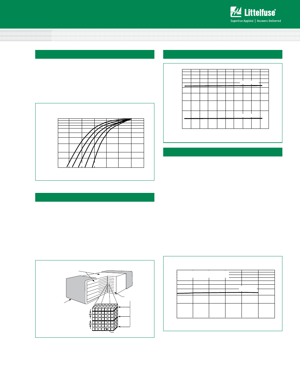
At low current levels, the V-I curve of the multilayer
transient voltage suppressor approaches a linear (ohmic)
relationship and shows a temperature dependent effect.
At or below the maximum working voltage, the suppressor
is in a high resistance modex (approaching 10
6
Ω at its
maximum rated working voltage). Leakage currents at
maximum rated voltage are below 100µA, typically 25µA.
100%
1E
-9
1E
-8
SUPPRESSOR CURRENT (A
DC
)
10%
1E
-7
1E
-6
1E
-5
1E
-4
1E
-3
1E
-2
25
50
75
100
125
o
C
SUPPRESSOR
VO
LT
A
GE IN PERCENT OF
V
NOM
V
ALUE
AT
25
o
C (%)
FIGURE 10. TYPICAL TEMPERATURE DEPENDANCE OF THE CHARACTERISTIC
CURVE IN THE LEAKAGE REGION
o
o
o
o
Clamping Voltage Over Temperature (V
C
at 10A)
100
10
20
V26MLA1206
40
60
80
100
120
140
TEMPERATURE (
o
C)
CLAMPING
VO
LT
AG
E
(V)
V5.5MLA1206
0
-20
-40
-60
FIGURE 12. CLAMPING VOLTAGE OVER TEMPERATURE
(V
C
AT 10A)
Typical Temperature Dependance of the Haracteristic
Curve in the Leakage Region
Speed of Response
The Multilayer Suppressor is a leadless device. Its response
time is not limited by the parasitic lead inductances found
in other surface mount packages. The response time of
the Z
N
O dielectric material is less than 1ns and the MLA
Automotive Series can clamp very fast dV/dT events such as
ESD. Additionally, in "real world" applications, the associated
circuit wiring is often the greatest factor effecting speed of
response. Therefore, transient suppressor placement within
a circuit can be considered important in certain instances.
GRAINS
DEPLETION
FIRED CERAMIC
DIELECTRIC
REGION
METAL
ELECTRODES
DEPLETION
REGION
METAL END
TERMINATION
FIGURE 11. MULTILAYER INTERNAL CONSTRUCTION
Multilayer Internal Construction
Energy Absorption/Peak Current Capability
Energy dissipated within the MLA Automotive Series is
calculated by multiplying the clamping voltage, transient
current and transient duration. An important advantage of
the multilayer is its interdigitated electrode construction
within the mass of dielectric material. This results in
excellent current distribution and the peak temperature per
energy absorbed is very low. The matrix of semiconducting
grains combine to absorb and distribute transient energy
(heat) (see Speed of Response). This dramatically reduces
peak temperature; thermal stresses and enhances device
reliability.
As a measure of the device capability in energy and peak
current handling, the V26MLA1206 part was tested with
multiple pulses at its peak current rating (150A, 8/20µs). At
the end of the test,10,000 pulses later, the device voltage
characteristics are still well within specification.
100
10
0
V26MLA1206
2000
4000
6000
8000
10000
12000
NUMBER OF PULSES
VO
LT
AG
E
FIGURE 13. REPETITIVE PULSE CAPABILITY
PEAK CURRENT = 3A
8/20 s DURATION, 30s BETWEEN PULSES
Repetitive Pulse Capability
Figure 8
Figure 9
Figure 10
Figure 11