Buyers B745236T User Manual
Page 2
3007985 Rev. A
SAFETY MESSAGE TO INSTALLERS AND USERS:
WARNING
Read, understand and follow all instructions shipped with
the products. In addition, listed below are some other
important safety instructions and precautions you should
follow:
• To properly install this light: you must have a good
understanding of automotive electrical procedures and
systems, along with proficiency in the installation and use
of safety warning equipment.
• When drilling into a vehicle structure, be sure that both
sides of the surface are clear of anything that could be
damaged.
• In order for the light to function properly, a separate
ground connection must be made. If practical, it should be
connected to the negative battery terminal. At a minimum,
it may be attached to a solid metal body or chassis part
that will provide an effective ground path as long as the
light system is to be used.
• Locate light control so the VEHICLE and CONTROL can
be operated safely under all driving conditions.
• Do not attempt to activate or deactivate light control
while driving in a hazardous situation.
• You should frequently inspect the light to ensure that it
is operating properly and that it is securely attached to the
vehicle.
• File these instructions in a safe place and refer to them
when maintaining and/or reinstalling the product.
Failure to follow all safety precautions and instructions
may result in property damage, serious injury, or death to
you or others.
UNPACKING
After unpacking the unit, examine it for damage that may
have occurred in transit. If the equipment has been dam-
aged, do not attempt to install or operate it; file a claim
immediately with the carrier stating the extent of the dam-
age. Carefully check all envelopes, shipping labels and tags
before removing or destroying them.
KIT CONTENTS LIST FOR PERMANENT MOUNT
Qty. Description
1 Grommet
2 Lockwasher, Int. tooth, #8
2 Nut, Hex, #8-32
INSTALLATION
WARNING
When installing equipment inside air bag equipped
vehicles, the installer MUST ensure that the equipment is
installed ONLY in areas recommended by the vehicle man
ufacturer. Failure to observe this warning will reduce the
effectiveness of the air bag, damage the air bag, or poten
tially damage or dislodge the equipment, causing serious
injury or death to you or others.
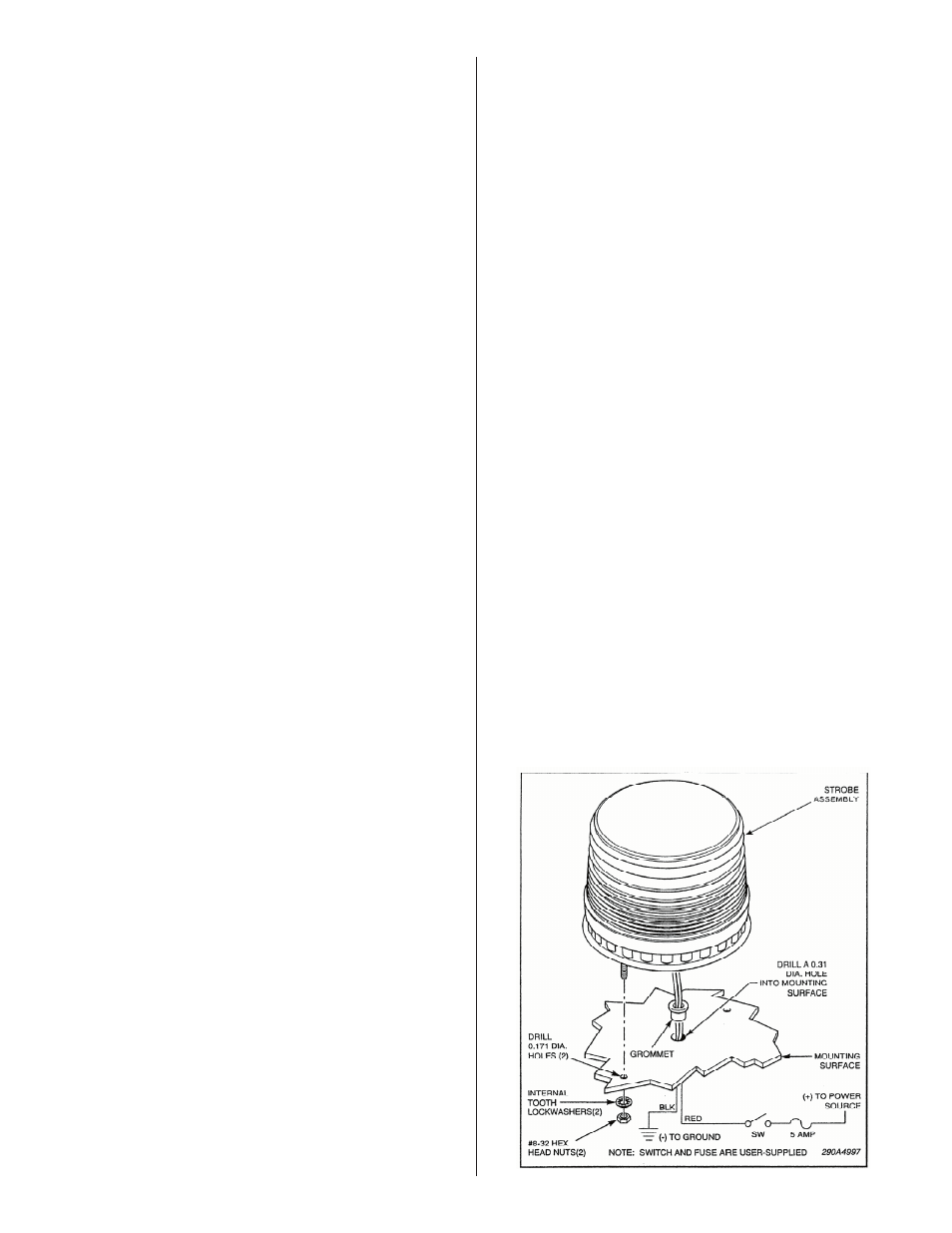
To install the light on the mounting surface, see figure 1
and proceed as follows:
A. Determine the strobe light mounting location.
B. Before proceeding, plan all wiring and cable routing.
C. Scribe a wire routing hole location on the mounting sur-
face at the center of the strobe light location. Scribe mount-
ing holes locations on the mounting surface 2.0-inches from
center on either side of the wire routing hole.
To avoid damage when drilling, ensure that both sides of
mounting surface are clear of any parts or wires.
Also, when drilling any holes, ensure that holes are drilled
only through sheet metal and not through upholstery.
D. Drill two 0.171” holes at the scribed mounting holes loca-
tions. Drill a 0.31” hole at the scribed wire routing hole loca-
tion. Remove all burrs and sharp edges.
E. Install the supplied grommet in the wire routing hole.
F. Route the red and black wires through the supplied grom-
met in the mounting surface. Apply a silicone sealing com-
pound around all holes in the mounting surface.
G. Connect the red wire to one terminal of a user-supplied
switch with a current handling capacity of at least two
amperes. Connect the black wire to the vehicle chassis as
close as practical to the light. Connect the remaining switch
terminal to the vehicle battery with user-supplied wire.
Install a user-supplied in-line fuse holder as close as practi-
cal to the battery. Install a 2 AMP fuse in the fuse holder.
NOTE
Polarity MUST be observed for proper operation. The red
wire connects to positive and the black wire connects to
negative. If the connections are reversed, the light will not
function.
Use 18-gauge wire for runs under 20-feet. For wire runs over
20-feet, consult local electrical codes.
Ensure that the vehicle’s supply voltage is within the voltage
rating specified on the strobe light.
H. Install the unit on the mounting surface using the
supplied lock washers and nuts. Test the light for proper
operation.
B745279T Strobe Lights
(Permanent Mount)