Truck, Trouble shooting guide, Fig. c wiring diagram – Buyers DBV3500 User Manual
Page 2
2
Truck
TM
by
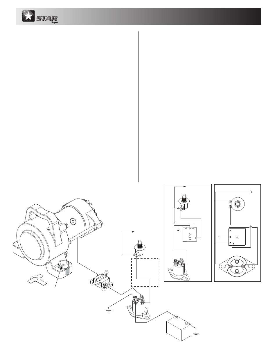
Fig. C Wiring Diagram
Ground
4 AWG
wire
4 AWG
wire
4 AWG wire
16 AWG
wire
16 AWG
wire
cab push button
switch SW900
to ignition switch
power source (fused)
13063171
Solenoid, 12V,
Motor Relay,
Continuous
manual reset
circuit breaker
CB150PB
vibrator
DBV2500/DBV3500
self grounding
through feet
Ground
install and bend lock
tabs as shown
apply medium/strong thread locker
torque to 280 ft. lbs.
Note: For wire lengths
exceeding 50 ft. it is
recommended to use
2 AWG wire.
tabs (as shown in Fig. "C") to prevent bolts from
loosening. Chain vibrator to body for added safety
(chain not included).
6. Wire vibrator per Figure "C" wiring schematic.
7. Install a chassis grounding strap for a more
positive ground. Adequate (4) AWG wire and (2)
additional terminals have been provided for this
purpose.
8. Optional Timer Installation: (Figure "D" or Figure "E")
a. Push button and timer should be mounted in the
cab in a convenient location.
b. The operating time (ON time) of the vibrator is
preset to 15 seconds for the optional timer.
c. To operate: press and release push button. The
vibrator will run for 15 seconds and stop. To run
the vibrator again wait 30 seconds, then press
button again.
d. Wire the timer and push button to truck’s
ignition for secured operation.
TROUBLE SHOOTING GUIDE:
1. Vibrator runs slow: Measure motor voltage. If less
than 12 volts DC, increase wire size from standard 4
AWG to 2 AWG.
Note: Installations requiring over
50’of wire use 2 AWG wire.
Inspect motor brushes and change as needed. Brush
life varies with duty cycle.
2. Loud, unusual vibrator noise: Make sure vibrator
bolts are tight. Inspect mounting plate for cracks.
Reinforce mounting plate and weld as needed. If
vibrator casting is cracked replace with new parts.
3. Vibrator fails to operate: Check vibrator to
make sure it is getting power. Check all electrical
connections (and ground) for secure corrosion free
connections. Vibrator is grounded through its foot.
Install grounding strap for a more positive ground.
Check cab push button switch, solenoid and circuit
breaker for proper operation. Note: 150 Amp circuit
breaker requires manual reset. If tripped, reset.
Maximum continuous run time is 15 seconds followed
by 30 seconds cooling time before operating again.
NOTE: Although the vibrator has o-ring seals and
the bearings are permanently lubricated, avoid
spraying vibrator directly with water and do not
pressure wash.
Optional 3011111
Timer Diagram
Optional 3022840
Timer Diagram
Fig. D
Fig. E
4 AWG
wire
16 AWG
wire
cab push button
switch SW900
Timer
3011111
to ignition switch
controlled power source
Ground
(-) GROUND
INITIION SWITCH CONTROL
POWER SOURCE (+)
16 AWG WIRE
CAB PUSH BUTTON
SWITCH SW900
12 V SOLENOID MOTOR RELAY
TIMER 3022840
see Fig D or E for
optional timer
installation