Trucks without factory bumpers figure 2, Trucks without factory installed bumper – Buyers 1801105 User Manual
Page 2
Quality since 1946
9049 Tyler Blvd. • Mentor, Ohio 44060
Phone (440) 974-8888 • Fax (440) 974-0165
Toll-Free Fax 800-841-8003 • buyersproducts.com
3009033 Rev. A
WARRAnTy
Buyers Products Co. warrants all truck/trailer hardware manufac-
tured or distributed by it, to be free from defects in material and
workmanship for a period of one year from date of shipment. Parts
must be properly installed and used under normal conditions. Any
product which has been altered, including modification, misuse,
accident or lack of maintenance will not be considered under
warranty. Normal wear is excluded. The sole responsibility of
Buyers Products Co. under this warranty is limited to repairing or
replacing any part or parts which are returned, prepaid, and are
found to be defective by Buyers Products Co. Authorization from
Buyers Products Co. must be obtained before returning any part.
No charges for transportation or labor performed on Buyers’ prod-
ucts will be allowed under this warranty.
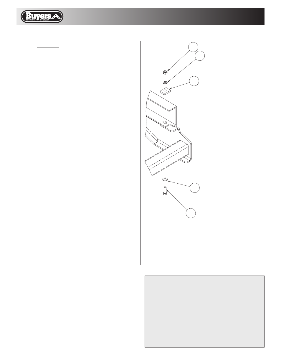
Trucks Without
Factory Bumpers
Figure 2
6
2
9
3
8
Trucks without factory installed bumper.
note: It may be necessary to relocate the license
plate mounting bracket in order to complete the
hitch installation.
1. Position the hitch against the frame and align the
hitch’s rear slots with the fore/aft slots in the rear of
the frame.
2. Fasten hitch to frame with two M14 x 40mm
screws, flat washers, lock washers, reinforcement
blocks and nuts in the hitch’s rear slots as shown in
figure 2. Do not tighten completely at this time.
3. Install two 9/16 x 2” screws, reinforcement
blocks, flat washers and lock nuts in the forward
most holes as shown in figure 1. Do not tighten
completely at this time.
4. For short bed trucks, the center hole must be
drilled at this time. For long bed trucks, skip to step 6.
Using the center hitch holes as a template drill two
9/16” holes in the frame. Be careful not to drill into
any lines or wire harnesses on the back side of the
frame.
5. Install two 9/16 x 2” screws, reinforcement
blocks, flat washers and lock nuts in the center
holes as shown in figure 1.
6. Using a torque wrench, torque the M14 CL10.9
bolts to 135 ft-lbs and torque the 9/16” G8 bolts to
120 ft-lbs.