Assembly instructions, Installation instructions – Buyers 4100-Series User Manual
Page 2
Quality since 1946
9049 Tyler Blvd. • Mentor, Ohio 44060
Phone (440) 974-8888 • Fax (440) 974-0165
Toll-Free Fax 800-841-8003 • buyersproducts.com
3008069 Rev. A
Warranty
Buyers Products Co. warrants all truck/trailer hardware manufac-
tured or distributed by it, to be free from defects in material and
workmanship for a period of one year from date of shipment. Parts
must be properly installed and used under normal conditions. Any
product which has been altered, including modification, misuse,
accident or lack of maintenance will not be considered under
warranty. Normal wear is excluded. The sole responsibility of
Buyers Products Co. under this warranty is limited to repairing or
replacing any part or parts which are returned, prepaid, and are
found to be defective by Buyers Products Co. Authorization from
Buyers Products Co. must be obtained before returning any part.
No charges for transportation or labor performed on Buyers’ prod-
ucts will be allowed under this warranty.
Cable routing notes
A. Make sure that the cable is not bent smaller
than a 6" radius. The cable should be as straight
as possible to minimize the force required to pull
the cable.
B. Make sure to route the cable away from hot
components like the engine block or exhaust pipes.
The recommended temperature range for the cable
is -65° to +215° Fahrenheit.
A
B
B
A
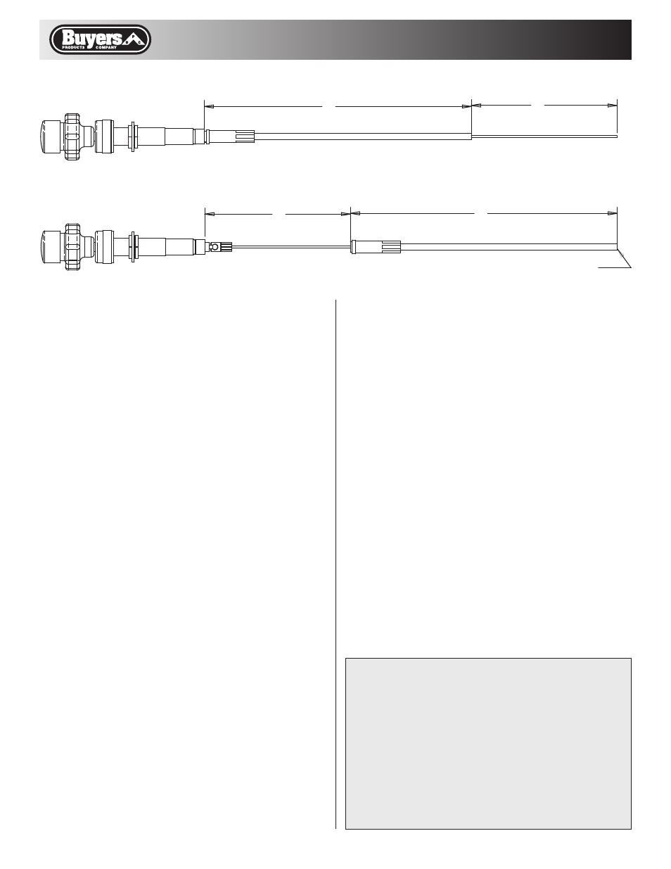
DESIRED CABLE LENGTHS
CUTTING CONFIGURATION
CUT THROUGH BOTH
CONDUIT AND CORE
WITH ABRASIVE WHEEL
assembly Instructions
1. Place O-ring on the end of the conduit fitting.
2. Hook spherical end of the control head into
socket on the end of the cable core.
3. Hold the O-ring in the notch on the conduit
fitting and press against the control head.
Tighten nut.
Installation Instructions
1. Drill .750-.781" diameter hole in the control panel
or dash board where you would like to mount the
cable. Make sure the control panel or dash board is
rigid and strong in the mounting location.
CaUtIOn: Be extremely careful not to drill into
any existing wires or components behind the
control panel or dash board.
2. Thread cable through the hole and route it
to the throttle control linkage. Tighten 3/4 nuts
against each side of the mounting surface. Tie
cable away from any moving or hot parts.
3. The end of the cable conduit must be mounted
near the throttle linkage to work properly. You may
use a conduit clamp or bulkhead fitting to hold the
conduit.
4. Attach cable core to throttle linkage with the
supplied throttle stop.