Fig. 7, Fig. 9 – Buyers 5051105 User Manual
Page 3
3
15. Repeat for the Driver Side installation. Re-install tail light
lens if it was removed earlier.
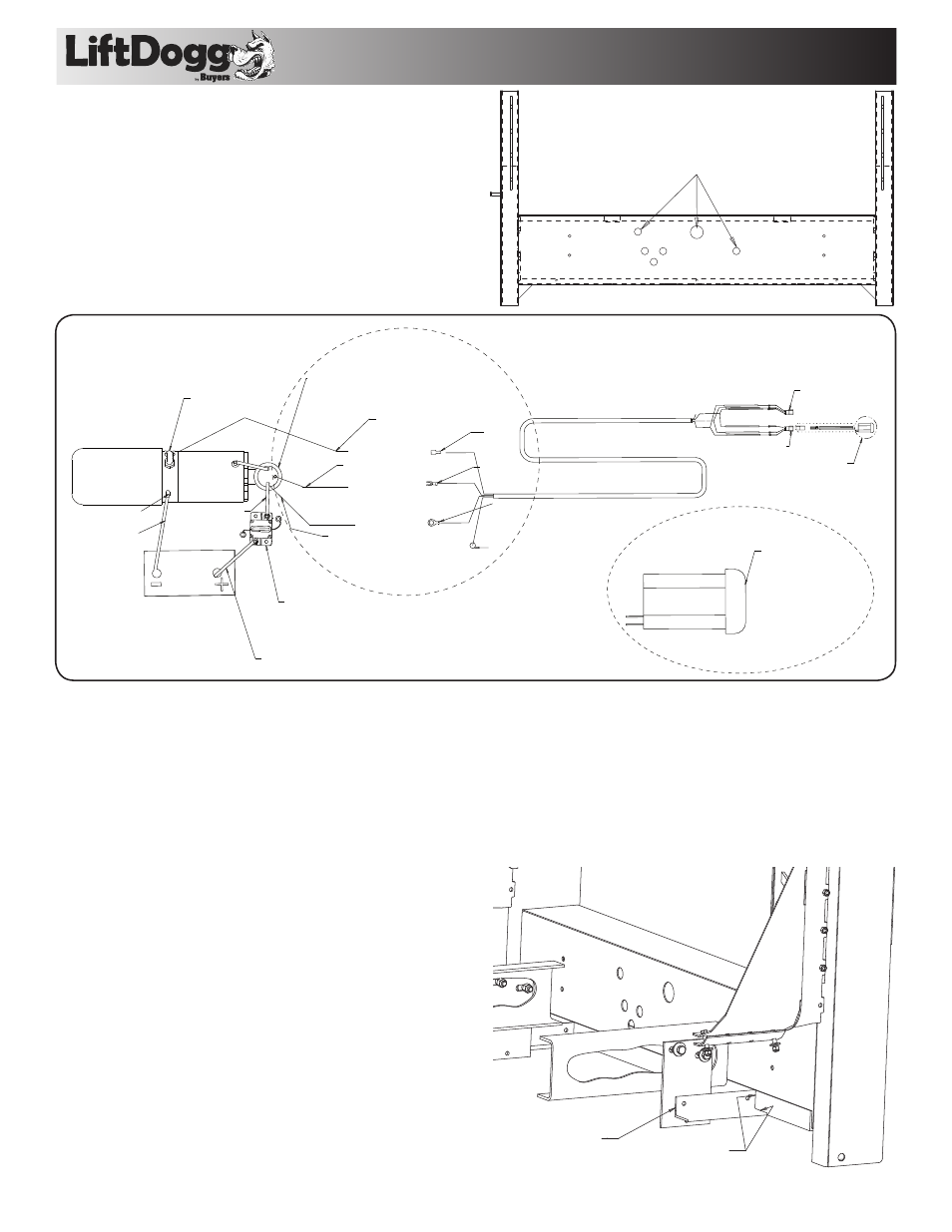
16. Verify the spare tire access holes to be available. (fig. 7)
a. Simply remove the license plate cover and check the
existing holes to allow you to get in through the hole.
17. Liftgate for wiring. (fig. 8)
a. Remove the 5/16 bolts holding the license cover. Pull out
the misc parts bag/box.
b. Review the Wiring circuit in the figure below.
Spare Tire Access Holes
Additional Holes May Need to be Cut if not Existing
Fig. 7.
HYD POWER UNIT
WELDING SHOULD DISCONNECT ALL BATTERY CABLES
ALWAYS DISCONNECT THE GROUND CABLE FIRST. ATTACH
THE GROUND TO THE TRUCK - NOT THE LIFTGATE
(1) WHITE WIRE ----> 1 TERMINAL
(2) BLACK -----> 2 TERMINAL
(3) RED -----> 7 TERMINAL
JUMPER 1 ---> 8 TERMINAL
THIS STEP IS DONE
IN MFG ASSEMBLY
BATTERY
ATTACH TO THIS TERMINAL
BLACK WIRE FOR POWER
MOTOR AND RAISE (2)
RED WIRE FROM
RELIEF COIL (3)
ATTACH THE RING TERMINAL
ENDS TO THIS SOLENOID
WHITE WIRE (+) COMING IN
RED (3)
BLACK (2)
WHITE (1)
NOTHING
PLUG USE FOR REMOTE
CONTROL OPTION ONLY
CONNECTION FOR
THE KEY SWITCH
(AVAILABLE STANDARD)
PUMP AND MOTOR
COMMON GROUND
LONG GROUND
BAT CABLE #4 AWG
LONG RED BAT CABLE
#4 AWG
CIRCUIT BREAKER WITH MANUAL RESET.
MOUNT NEAR BATTERY
- MAY HAVE TO DRILL SMALL HOLES
- ATTACH TO FIREWALL THROUGH MOUNT
HOLES
A SHORT BAT CABLE
CONNECTION
LOWERING VALVE WITH
SOLENOID COIL
HIGH VOLTAGE
MAIN SOLENOID
FOR MOTOR
SEE DETAIL A
DETAIL A
[--->] CLOCK WISE TO RAISE
ACTUATE TERMINAL 1-2
[<---] C-CLOCK WISE TO LOWER
ACTUATE TERMINAL 7-8
Fig. 8.
18. Install the circuit breaker on the vehicle fender,
firewall or inside the engine compartment away
from moving parts [near battery]. Make sure there
will be room for the wires to be installed and the reset
button is accessible.
19. Loosen the strain relief conduit in the back of the liftgate
box. Pull the 4awg wire through the hole-leaving about 2
inches of slack for easy access. Tighten the conduit again.
20. Run the wire underneath the truck and along the frame
structure of the truck. Pull the wire beyond the battery
location
21. Split the negative and the positive wires to prepare them
for attachment to battery.
22. Cut the positive wire length needed to reach the
auxiliary terminal of the circuit breaker installed earlier. Cut
the remaining positive wire long enough to reach from the
breaker to the positive Battery terminal. Cut the negative
wire to the needed length to the battery terminal.
23. Install the lower mount onto the frame. Remove the
slotted bracket plates from the liftgate. This is located next
to the hydraulic unit.
24. Bolt the Bracket plates to the Frame where the holes
are available (if not Drill). You may have to do simple
modification to the plates.
25. Clamp the short angle irons to the bracket plates. The short
angle acting as an extension arm to the slotted angle irons.
26. Tackweld the bracket plates to the short angle irons; and
tack weld the short angle iron to the main long angle iron.
27. Remove the tacked brackets by removing the bolts just
installed earlier.
28. Weld all seams with a 1/4" fillet weld.
29. Secure the Welded Brackets back onto the truck frame
and the bottom of the Lift Gate. (fig. 9)
30. Install the license plate light onto the cover. Wiring is not
provided for this accessory.
Weld Angle to
Mounting Plate
Weld Angle Feet
to Main Mounting Angle
Fig. 9.