4 operation, 1 hardware, 5 adjust system levels – Crown Audio IQ-PIP-USP2 User Manual
Page 8
IQ-PIP-USP2
Page 15
IQ-PIP-USP2 Reference Manual
IQ-PIP-USP2
Page 14
IQ-PIP-USP2 Reference Manual
4 Operation
With an IQ-PIP-USP2 module,
your Crown amplifier can be moni-
tored and controlled from a remote
location through the use of an IQ
System. This
PIP
module features
SmartAmp
™
capabilities which will
enable the amplifier to function au-
tomatically. For example, the IQ-PIP-
USP2 can automatically turn off the
high voltage supplies of the amplifier
when no input signal is present. This
can lower electrical usage and pro-
vide long-term cost savings. The IQ-
PIP-USP2 can also automatically
limit the audio signal and detect and
report various problems.
The IQ-PIP-USP2 also features digi-
tal signal processing capabilities
including signal delays and a wide
variety of filters.
In addition, the IQ-PIP-USP2
Load Supervision feature has the
ability to verify the status of the loads
in real time.
The IQ-PIP-USP2 uses Crown’s IQ2
protocol. This makes it possible for a
user to design custom graphic dis-
play modules to control and monitor
the unit with IQ2-compatible IQ soft-
ware. This allows even greater flex-
ibility within Crown’s IQ software via
custom control pages. Plus, the IQ2
protocol provides for third-party pro-
gramming for system controllers
such as those from AMX and
Crestron.
The following sections describe the
IQ-PIP-USP2 features and opera-
tion. Where specified, some features
are accessed via controls located
on the unit itself. However, many of
the features can be controlled or
configured using IQ for Windows soft-
ware. Commands are transmitted
via an IQ interface to the specified IQ
component (an IQ2-compatible in-
terface is required). Please contact
your Crown representative or
Crown’s Technical Support Group if
you are unfamiliar with IQ software.
4.1 Hardware
4.1.1 Data Signal Presence
Indicator
An amber Data Signal Presence In-
dicator (DATA) is provided on the
front panel. It flashes whenever com-
mands addressed to the IQ-PIP-
USP2 are received. To assist with
troubleshooting, an option that
forces the DATA indicator to remain
lit is available through IQ software.
4.1.2 Preset Indicator
A green PRESET indicator is pro-
vided on the front panel. This indica-
tor signals the number of the cur-
rently selected preset by emitting a
series of flashes which match the
preset number, followed by a pause.
The indicator will continuously re-
peat the number selected until a
change is made to any setting.
4.1.3 Crown Bus Input/Output
Connector
An RJ-45 connector provides both
input and output connection to the
Crown Bus. This connector is used
for input in a conventional Crown
Bus wiring configuration, and can
be used for both input and output
when a “hub” style Crown Bus wir-
ing configuration is implemented
(see Section 5.2). Drop-out relays
maintain loop integrity in the event
power is removed from the IQ-PIP-
11. Connect the audio signal
wiring to the IQ-PIP-USP2. Two
female XLR connectors, one for
each channel, are provided for
signal input. Two male XLR
connectors, one for each channel,
are provided for audio daisy
chaining. See Section 5.1 for more
information on audio wiring.
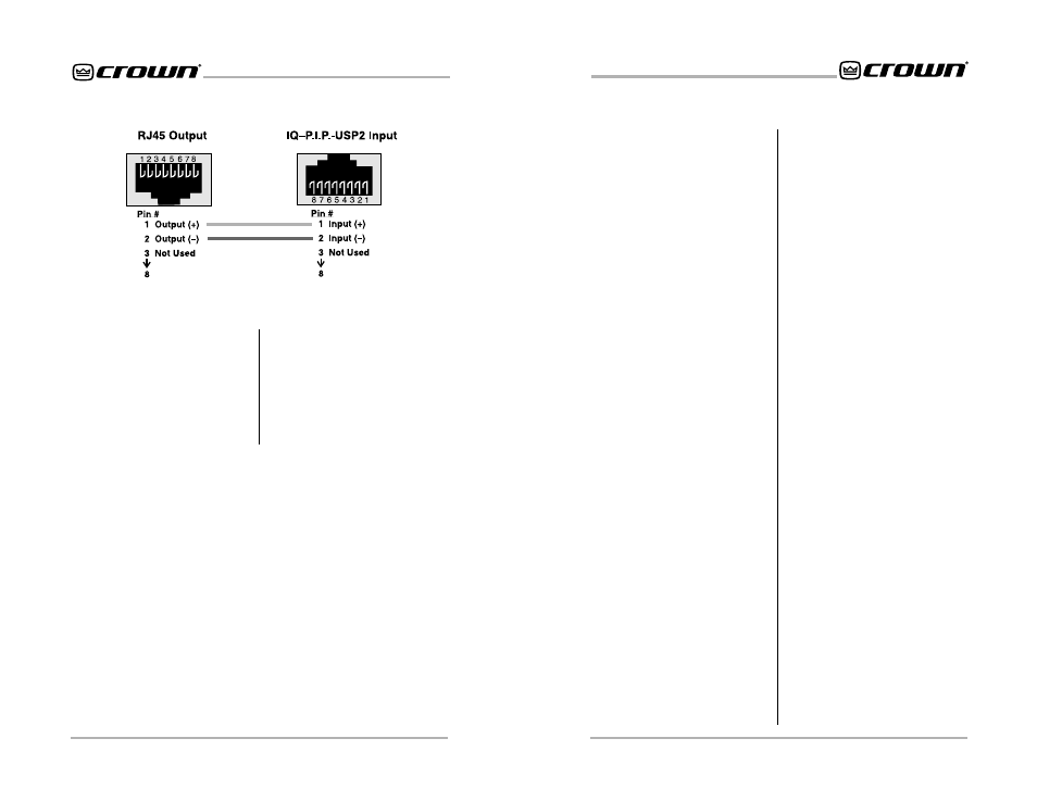
Figure 3.11 RJ-45 Output to RJ-45 Input.
12. Reconnect amplifier to the AC
receptacle.
3.5 Adjust System Levels
13. Adjust attenuator levels both on
the amplifier and on the IQ-PIP-
USP2 control panels within your IQ
software for optimum system gain.