Crown Audio IQ-PIP-USP2 User Manual
Page 12
IQ-PIP-USP2
Page 23
IQ-PIP-USP2 Reference Manual
IQ-PIP-USP2
Page 22
IQ-PIP-USP2 Reference Manual
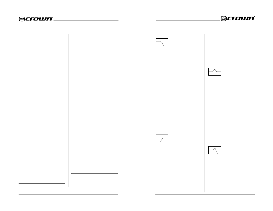
Low-Pass Crossover Filter
Description: This filter rolls off high
frequencies at a rate determined by
the shape parameter. The filter is
commonly used to feed the low fre-
quency portion of an audio signal to
woofers or subwoofers. It can be
combined with a high-pass cross-
over filter to create a band-pass
crossover filter for driving mid-range
drivers.
Passband gain: Fixed at unity.
Frequency: Sets the –3 dB corner
frequency of the filter. The range is
20 Hz to 20 kHz.
Shape: Sets the response shape of
the filter. Available response shapes
are: 1st-order Butterworth, 2nd-or-
der Butterworth, 3rd-order
Butterworth, 4th-order Butterworth,
2nd-order Bessel, 3rd-order Bessel,
4th-order Bessel and 4th-order
Linkwitz-Riley.
High-Pass Crossover Filter
Description: This filter rolls off low
frequencies at a rate determined by
the shape parameter. The filter is
commonly used to feed the high
frequency portion of an audio signal
to horns or tweeters. It can be com-
bined with a low-pass crossover fil-
ter to create a band-pass crossover
filter for driving mid-range drivers.
Passband gain: Fixed at unity.
Frequency: Sets the –3 dB corner
frequency of the filter. The range is
20 Hz to 20 kHz.
Shape: Sets the response shape of
the filter. Available response shapes
are: 1st-order Butterworth, 2nd-or-
der Butterworth, 3rd-order
Butterworth, 4th-order Butterworth,
2nd-order Bessel, 3rd-order Bessel,
4th-order Bessel and 4th-order
Linkwitz-Riley.
Parametric Equalization Filter
Description: This filter boosts or cuts
a relatively narrow frequency band
like a band-pass filter. It is com-
monly used to correct specific
anomalies in the response of driv-
ers.
Passband Gain: Sets the amount of
boost or cut for the filter. The range
is +12 dB to –24 dB.
Frequency: Sets the center fre-
quency of the filter. The range is 20
Hz to 20 kHz.
Q: Sets the width and slope of the
filter. The range is 0.1 to 30. The
lower the Q, the wider the filter and
the better the transient response
and visa versa.
Low-Pass Equalization Filter
Description: This filter combines the
functions of the parametric equal-
ization filter to boost or cut a rela-
tively narrow frequency band with a
low-pass filter to roll of the frequen-
cies above the center frequency.*
Frequency: Sets the center fre-
quency of the filter. The range is 20
Hz to 20 kHz.
On/Off: Turns this function on or off.
Threshold: Sets the threshold, in
dB, above which the compressor
acts. The level is measured at the
input to the
PIP
and corresponds to
the level shown on an input meter.
The compressor is “feed-forward,”
meaning that the level detection point
is located before the gain control
stage. The range is from +16 dBu to
–40 dBu.
Attack Time: Sets the attack time of
the compressor. The attack time is
defined as the time it takes the com-
pressor to attenuate the input signal
by 10 dB. The range is from 1 milli-
second to 2 seconds.
Release Time: Sets the release time
of the compressor. The release time
is defined as the time it takes the
compressor to increase the input
gain by 10 dB. The range is 100
milliseconds to 30 seconds.
Compressor Ratio: Sets the com-
pression ratio for the compressor.
The range is 1, 2, 4, 8, 16, 32,
∞ to 1.*
4.4.5 Programmable Filters
Each channel can have as many as
eight different cascaded filters (the
actual number depends on the mix
of filters chosen). There are seven
different filter types from which to
choose.
Low-Pass Crossover Filter (1st–
4th order)
High-Pass crossover Filter (1st–
4th order)
Parametric Equalization Filter (2nd
order only)
Low-Pass Equalization Filter (2nd
order only)
High-Pass Equalization Filter (2nd
order only)
Low-Pass Shelving Equalization
(1st order only)
High-Pass Shelving Equalization
(1st order only)
DSP filters can be processed pre or
post crossover, depending upon
which form the IQ-PIP-USP2 is con-
figured in (see the IQ for Windows
documentation for more information
about forms).
All filters have IIR based topologies
to insure a proper magnitude/phase
relationship for use in professional
audio applications such as equal-
izer or crossover (dividing) networks.
Each channel has a total of eight
“biquad” filter cells.**
All filters with adjustable Q-factors
can be set in fractions of an octave.
See Section 5.4 for information about
calculating Q-factors.
An indicator in the software shows
how much DSP resources are being
used by the selected filters. One 3rd
or 4th order filter uses the equivalent
of two 1st or 2nd order filters.
1st, 2nd, 3rd and 4th-order re-
sponses result in 6, 12, 18 and 24
dB/octave roll-offs, respectively.
A description and list of the param-
eters of each filter type are pre-
sented next:
** “Biquad” refers to the double quadratic
equations which mathematically de-
scribe each filter implemented in the
digital signal processor.
* 1:1 is the same as “off.”