5 load supervision – Crown Audio IQ-PIP-USP2 User Manual
Page 14
IQ-PIP-USP2
Page 27
IQ-PIP-USP2 Reference Manual
IQ-PIP-USP2
Page 26
IQ-PIP-USP2 Reference Manual
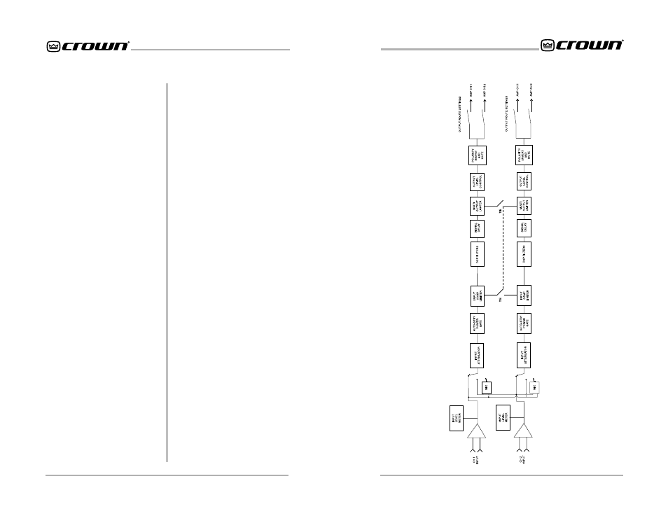
Figure 4.2 IQ-PIP-USP2 Signal Flow Block Diagram
dB in ½-dB steps.
4.4.11 Output Trim Controls
An output trim control is provided for
each channel to adjust the output
gain after processing, allowing for
“make-up” gain to compensate for
losses due to crossovers, etc. Range
is +12 dB to –80 dB in ½-dB steps.
4.4.12 Tie Switch
The Tie switch connects all active
compressors and limiters together
so that any limiting/compression af-
fects the signal on both channels,
such as would typically be desired
when processing stereo signals.
4.5 Load Supervision
The Load Supervision feature allows
real time monitoring of the load con-
nected to each amplifier channel.
When enabled, the IQ-PIP-USP2
continuously monitors the amplifier
output voltage and current and cal-
culates the long-term average load
impedance. The measured load im-
pedance is compared against user
defined high and low limits. If either
limit is exceeded, the status indica-
tor and/or IQ System error reporting
functions alert the user of the prob-
lem. There are six controls and two
indicators for each channel:
On/off: Turns the Load Supervision
feature on or off.
High Limit: Sets the upper bound
above which the system will report a
“high” error status.
Low Limit: Sets the lower bound
below which the system will report a
“low” error status.
Nominal Load Impedance: Sets the
expected average impedance for
the connected load. This value de-
termines the output signal level re-
quired for test. This parameter is
also used by the average power lim-
iter to determine the expected power
limit threshold. See Section 4.4.8
Calculate: This button invokes an
impedance calculator. Entering out-
put voltage and power will give the
expected impedance.
Include in Standard Error Report-
ing: Enables error reporting so that
any high/low status condition is re-
ported via the IQ System (See Sec-
tion 4.3.15).
Report to Aux: Enables any high/
low status condition to be reported
via the IQ-PIP-USP2 aux port output
(See Section 4.1.7).
Test Indicator: This indicator lights
when the load supervision algorithm
is actually performing a load imped-
ance calculation and test verifica-
tion.
Low/Normal/High Indicator: This
indicator shows the present status
of the load with respect to the user
defined high/low limits.
Z avg Monitor: Reports actual cal-
culated average load impedance.