6 q-factor calculation, 7 load supervision applications – Crown Audio IQ-PIP-USP2 User Manual
Page 18
IQ-PIP-USP2
Page 35
IQ-PIP-USP2 Reference Manual
IQ-PIP-USP2
Page 34
IQ-PIP-USP2 Reference Manual
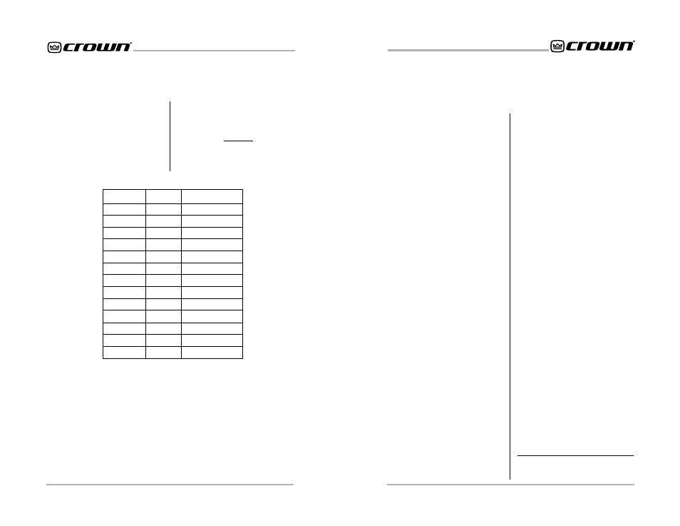
5.6 Q-Factor Calculation
Many of the DSP filters on the IQ-
PIP-USP2 feature adjustable Q-fac-
tor, which is a measure of the filter’s
selectivity or sharpness. Q-factor is
adjustable in fractions of an octave
on the IQ-PIP-USP2.
Use the table in Figure 5.9 to deter-
mine Q-factor for a given bandwidth
in octaves. The table relates the Q-
factor to bandwidth in octaves ac-
cording to the equation:
where K is the number of equal divi-
sions per octave.
Figure 5.9 Q-factor vs.Bandwidth
2
(1/2K)
1
(1/K)
–1
Q=
Q-factor
0.200
0.266
0.667
1.414
2.415
2.871
4.318
8.651
14.42
28.85
43.28
50.00
100.0
K
0.21
0.25
0.5
1
1.5
2
3
6
10
20
30
34.7
69.3
BW in Octaves
4.8
4
2
1
2/3
1/2
1/3
1/6
1/10
1/20
1/30
1/35
1/70
5.7 Load Supervision
Applications
The IQ-PIP-USP2 Load Supervision
feature can be used to monitor the
amplifier load in real time with al-
most any program material. Aver-
age load impedance is calculated
as a function of amplifier output volt-
age and current. The system re-
quires approximately 20-30 mA of
average amplifier output current for
adequate supervision. This allows
typically low average output power
levels of less than ½ watt with most
loads. The maximum load imped-
ance for reliable system perfor-
mance is limited to about 50 ohms.
Higher impedances can be mea-
sured but may require higher ampli-
fier output levels for reliable opera-
tion.
Most amplifier/load systems can be
configured and supervised by fol-
lowing these steps:
1 Configure your audio system
using a known “good” load, then
enable the Load Supervision
feature.
2 Provide typical program material
at a level high enough to light the
“test” indicator.
3 Run the system at this level until the
average impedance stabilizes.
This may take seconds to minutes
depending on level, duty-cycle,
etc.
4 Set the nominal impedance at the
measured value average. This
optimizes the supervision
algorithm for voltage and current
levels versus the actual load Note:
a higher nominal setting will
require higher output levels.
5 Set the high limit at twice average
and the low limit at one-fourth
nominal.*
6 Let the system run for extended
periods using any and all typical
program material.
7 Adjust the high/low limits, if
necessary, to account for any
variance in average measured
impedance.
8 Enable error reporting, if desired.
This procedure should work well for
most applications. However, some
applications can be a little more
difficult. Some very low-level and/or
low duty-cycle signals may not ad-
equately “test” the load. Lab and
situation testing have shown output
levels as small 40 dB below rated
amplifier output to be enough for
most low-impedance loads. Higher
impedance loads such as those used
in “lightly-loaded” 70V distribution
lines may require signal level near
20 dB below rated output.
The “Nominal Load Impedance” con-
trol is used to optimize the system
for the most accurate calculation of
load impedance. It should be set to
the expected nominal (or rated) im-
pedance of the “normal” load. The
high limit should be set for at least 2
times the expected nominal or ac-
tual measured load, while the low
limit should be set to ½ the expected
nominal or actual measured load.
* These limits are somewhat arbitrary but
should be a good starting point.