4 listen bus – Crown Audio IQ-PIP-USP2 User Manual
Page 17
IQ-PIP-USP2
Page 33
IQ-PIP-USP2 Reference Manual
IQ-PIP-USP2
Page 32
IQ-PIP-USP2 Reference Manual
* A negative signal can also be used as a
logic low because the signal is inter-
nally clamped to protect the internal
circuitry.
relay would then turn the fans on or
off. This is shown in Figure 5.5.
By monitoring the operating condi-
tion of amplifiers with the IQ System
software, the need for additional
cooling would be apparent. The
same software could then be used
to turn on the appropriate AUX con-
nector. (For more information about
turning the auxiliary feature on/off,
consult the IQ for Windows software
documentation.)
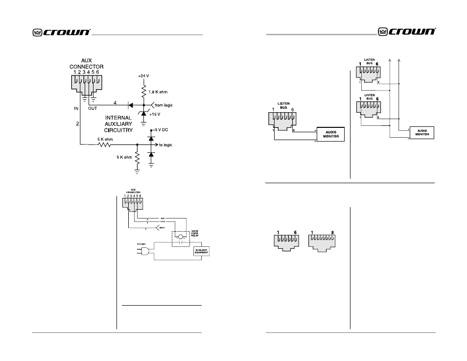
5.3.2 AUX Input
Depending on the IQ software being
used, the AUX connector can be
used to sense the presence of an
input signal across pins 2 (+) and 5
(ground). A +5 to +15 VDC signal at
the input will be interpreted as a
logic “high” and will be communi-
cated to the Crown Bus where a host
Figure 5.4 The Internal AUX Circuit
Figure 5.6 Listen Bus Connection
Figure 5.5
A Sample AUX Output Circuit
5.4 Listen Bus
Use the diagram in Figure 5.6 to
connect an audio monitoring sys-
tem, such as a headphone preamp,
to the IQ-PIP-USP2 Listen Bus.
computer or controller can act upon
it. A signal less than +1.6 VDC is
interpreted as a logic “low.”*
5.5 Working with RJ-11
and RJ-45 Connectors
Pin assignments for standard RJ-11
and RJ-45 connectors are indicated
in Figure 5.8.
Amp 1
Amp 2
Figure 5.7 demonstrates how mul-
tiple amplifiers can be monitored
using the Listen Bus. Crown’s IQ for
Windows software allows you to se-
lect the amplifier and channel you
wish to monitor.
Figure 5.7 Multiple -Amp Listen
Bus Configuration
When wiring RJ-45 connectors, it is
good practice to follow the EIA/TIA
568B protocol for RJ-45 connector
cable. This protocol assigns wire
colors as follows:
1 white-orange
5 white-blue
2 orange-white
6 green-white
3 white-green
7 white-brown
4 blue-white
8 brown-white
Extra care must be taken when at-
taching RJ-11 and RJ-45 connec-
tors to cable. Make sure you use the
appropriate crimping tool and verify
that the connector is properly seated
into the tool, or damage will result.
Contact Crown Technical Support
for additional information about work-
ing with RJ-11 and RJ-45 connec-
tors.
When wiring RJ-11 connectors, it is
good practice to follow the USOC
protocol for RJ-11 connector cable.
This protocol assigns wire colors as
follows:
1 white-green
4 white-blue
2 white-orange
5 orange-white
3 blue-white
6 green-white
RJ-11
RJ-45
Figure 5.8 RJ-11 & RJ-45 Pin
Assignments