3 install the iq-pip-usp2 into the amplifier, 2 prepare the amplifier, 4 install the wiring – Crown Audio IQ-PIP-USP2 User Manual
Page 6
IQ-PIP-USP2
Page 11
IQ-PIP-USP2 Reference Manual
IQ-PIP-USP2
Page 10
IQ-PIP-USP2 Reference Manual
5. Remove the existing
PIP
from
the amplifier back panel (two
screws). This may involve
disconnecting the
PIP
from a PIP2
input adapter. If a PIP2 input
adapter is already present,
remove the ribbon cables from the
adapter.
3.3 Install the IQ-PIP-USP2
into the Amplifier
6. Carefully ground yourself to the
chassis of the amplifier before
installing the IQ-PIP-USP2. It is a
good idea to maintain ground
contact between yourself and the
amplifier while inserting the
module into the amplifier.
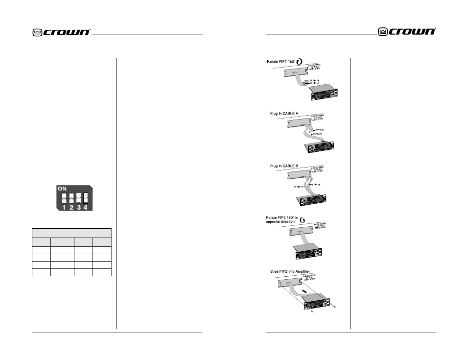
7. Install the IQ-PIP-USP2
into the
amplifier:
Turn the IQ-PIP-USP2 over so that
you can clearly see the two ribbon-
cable connectors located on the
underside of the circuit board (see
Figure 3.4). Connect the two input
ribbon cables of the amplifier. The
20-pin cable (A) should be
connected first, then the 18-pin
cable (B) should be connected.
Both ribbon cables should run
smoothly from the amplifier to the
PIP
card (see Figure 3.4).
Important: Be careful when
attaching the ribbon cable to the
connector that the cable is
Figure 3.4 Installing the
IQ-PIP-USP2
3.2 Prepare the Amplifier
3. Turn down the level controls (full
counterclockwise) and turn off the
amplifier.
4. Disconnect the amplifier’s
power cord.
A valid IQ address is any number
from 1 to 250. Do not use a number
higher than 250 since they are
reserved for special use. An
address of “0” (zero) should only
be used for “stand alone” mode.
Setting the address switch to “0”
disables the IQ bus port.
2. Set the scaling switch S3. Input
and output scaling is adjusted via
this four-segment switch. The
word “ON” is printed on the switch
along its upper left side to indicate
the ON position and the switches
are numbered along the bottom
(Figure 3.2). Refer to the chart in
Figure 3.3 for possible scaling
combinations. The factory-default
setting is +20 dBu. Figure 3.2
shows S3 set for +20 dBu.
S3
Figure 3.2 Scaling Switch (S3)
g
n
i
l
a
c
S
t
u
p
t
u
O
/
t
u
p
n
I
h
c
t
i
w
S
n
o
i
t
c
n
u
F
u
B
d
0
2
+
u
B
d
0
1
+
1
t
u
p
n
I
1
H
C
N
O
F
F
O
2
t
u
p
n
I
2
H
C
N
O
F
F
O
3
t
u
p
t
u
O
1
H
C
F
F
O
N
O
4
t
u
p
t
u
O
2
H
C
F
F
O
N
O
Figure 3.3 Scaling Chart
properly seated before applying
pressure to the connector.
Forcing the cable onto the
connector could cause the keying
tabs, which ensure proper pin
alignment, to break. Connecting
the ribbon cables with improper
pin alignments may result in
damage to the
PIP
.
When both cables are firmly
attached, turn the IQ-PIP-USP2
back to an upright position and
insert into the
PIP
opening in the
back of the amplifier. Take care
while inserting the
PIP
to make
sure you do not crimp, pinch or
stretch the ribbon cables.
8. Tighten the two PIP mounting
screws until the
PIP
is secured to
the amplifier back panel. Be sure
to use the supplied star-
washers for good ground
connection.
9. Reconnect the amplifier to the
AC receptacle.
3.4 Install the Wiring
10. Connect the IQ-PIP-USP2
to
the IQ system via the Crown
Bus. The IQ components in a
Crown Bus loop are wired
sequentially. The loop begins and
ends with the IQ interface. The
output of one IQ component
“loops” to the input of the next and
so on as shown in Figure 3.5.
There are three different types of
connectors used for Crown Bus
wiring on IQ components. These
include DIN connectors, screw
terminal plugs, and RJ-45
connectors. The IQ-PIP-USP2
As an option, switches 1, 2, 3 and 4
may be all set to the ON position,
which provides +20 dBu
headroom on the input, reduces
gain in the output gain stage by 10
dB, and improves system noise
floor.