5 iq audio in depth, 2 a closer look at crown bus wiring, 1 a closer look at audio signal wiring – Crown Audio IQ-PIP-USP2 User Manual
Page 15
IQ-PIP-USP2
Page 29
IQ-PIP-USP2 Reference Manual
IQ-PIP-USP2
Page 28
IQ-PIP-USP2 Reference Manual
•
The same IQ address can be used
more than once (once per loop per
model).
Single Loop Advantages
(with IQ-INT II interfaces)
•
The IQ System can send and
retrieve data faster in a single loop.
•
“Real time” level display of a
greater number of units is
possible.
The IQ-PIP-USP2 can be connected
to the Crown Bus with inexpensive
twisted-pair wiring (shielded or
unshielded). If fiber optic wiring is
required contact the Crown Techni-
cal Support Group (see page 2).
Here are some guidelines for twisted-
pair wiring:
•
Use shielded twisted-pair wire at
least 26 AWG in size when
interference is a problem. The wire
should be of good quality and
should have low capacitance—30
picofarads/foot or less is good.
(West Penn 452 or an equivalent
wire works well.) The shield serves
two purposes: First, it helps
5.2 A Closer Look at
Crown Bus Wiring
The IQ-PIP-USP2 must be con-
nected to a Crown Bus loop having
an IQ2-compatible IQ interface in
order for the IQ System to control or
monitor it. The Crown Bus is a serial
communication loop designed to
transmit IQ commands and data. As
implemented in the IQ-PIP-USP2, it
is a 20 milliamp current loop operat-
ing at a BAUD rate of 38.4 K. The
loop must be unbroken to function
properly.
If the system includes an IQ–INT II
interface, it can accept eight differ-
ent Crown Bus loops or zones. Di-
viding the sound system into differ-
ent zones, each with its own Crown
Bus loop, can have several advan-
tages. The following list contrasts
those advantages with those of a
single loop.
Multiloop Advantages
•
A break in communication in one
loop does not affect other loops.
•
Over 250 IQ components of the
same type can be used in a
system.
5 IQ Audio In Depth
This section provides additional in-
formation about Crown’s IQ System
with special guides to aid in the
•
When using unbalanced lines,
keep the cables as short as
possible. Avoid lengths greater
than 10 feet (3 meters).
•
Do not run audio input cables
together with high-level wiring
such as loudspeaker wires or AC
cords. (This lessens the chance of
hum or noise being induced into
the input cables.)
•
Do not connect audio and data
grounds together. For example,
do not connect the audio ground to
the Crown Bus ground.
installation and use of the IQ-PIP-
USP2. For more information about
any of these topics, contact Crown
Technical Support.
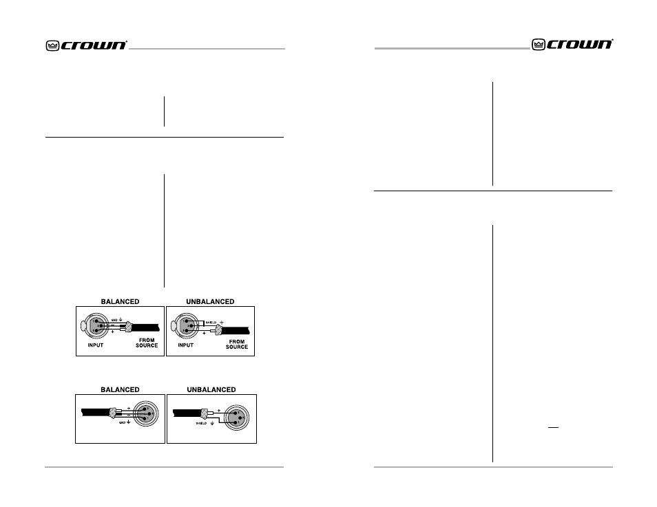
5.1 A Closer Look at Audio
Signal Wiring
Balanced XLR connectors are pro-
vided for audio input connection.
The audio cables should be wired in
one of the following manners (see
Figure 5.1):
We strongly recommend that bal-
anced wiring be used if possible.
Some important guidelines follow:
•
Always use shielded wire. The
higher the density of the shield
(the outer conductor), the better.
Spiral wrapped shield is not
recommended.
TO
INPUT
TO
INPUT
OUTPUT
OUTPUT
Figure 5.2 Audio Output Wiring
Figure 5.1 Audio Input Wiring
•
Turn the entire sound system off
before changing any connections.
Turn the level controls down
before powering the system back
up. Crown is not liable for damage
incurred when any transducer or
component is over-driven.
Balanced XLR connectors are pro-
vided for “daisy chain” audio con-
nection. The audio cables should be
wired in one of the following man-
ners (See Figure 5.2):
DO NOT USE THE CHANNEL 2
INPUT if the amplifier is used in
either Bridge-Mono or Parallel-Mono
mode.
For additional information on audio
input connection please refer to the
amplifier’s
Reference or Owner’s
Manual. It contains helpful informa-
tion on preventing unwanted sub-
sonic frequencies, radio frequency
interference, ground loops, and
feedback oscillation.