A.5 - gain and relay jumpers, 220i, Appendix – dbx DriveRack 220i User Manual
Page 52
48
220i
DriveRack
®
User Manual
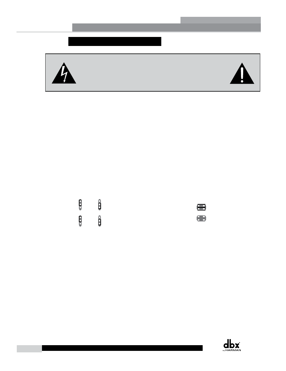
A.5 - Gain and Relay Jumpers
CAUTION: These servicing instructions are for use by qualified service
personnel only. To reduce the risk of electric shock, do not perform any
servicing other than that contained in the operating instructions unless you
are qualified to do so. Refer all servicing to qualified service personnel.
Disconnect mains power before servicing.
The 220i DriveRack gives you the option of changing the input gain level settings. There are 2 hardware
configurable gain settings. They are: +4 dBu, -10 dBV. For these cases, use the following procedure to
change the gain level settings. Please be advised however, that once the gain level has been changed
from the factory settings, the output meters will no longer be calibrated correctly.
You can configure the unit to pass audio when it is not powered up. Please refer to the information
below. You can also configure the unit to not pass audio when the power is off (Relay Bypass); the
normal mode is Relay bypass.
To change the the gain level or relay jumpers move the jumpers to the desired settings.
1. First, make sure that the unit has been shut off and unplugged prior to opening the unit.
2. Ground yourself prior to opening the 220i chassis to prevent ESD damage.
3. Open the chassis by removing 4 screws on each side of the chassis, as well as the top center
allen screw located on the front panel.
4. Locate the jumper block shown in the illustration below:
220i Main Board
Input Jumpers
Bypass Jumpers
Input/Ouput
Jumpers Levels
+14dBu
+22dBu
+30dBu
+14dBu
+22dBu
+30dBu
+14dBu
+22dBu
+30dBu
+14dBu
+22dBu
+30dBu
+14dBu
+22dBu
+30dBu
+14dBu
+22dBu
+30dBu
+14dBu
+22dBu
+30dBu
+14dBu
+22dBu
+30dBu
Audio Bypassed
Audio Not Bypassed
+4dBu
-10dBv
+4dBu
-10dBv
Jumper Locations:
• Input and Output jumpers are located at P4, P8, and P6 for Channel 1 and at P5, P9 and P13 for
Channel 2.
• Bypass Jumpers are located at P7 for Channel 1 and P12 for Channel 2.
NOTE:
There are two jumper blocks per input and one jumper block per output
Appendix