Diagram #5, Diagram #4, Diagram #6 – Derale Performance Single Mount 3__8" NPT Ports Up Remote Transmission Filter Kit, Premium User Manual
Page 2: Back view
Derale Performance, Los Angeles, CA
800.421.6288 www.derale.com
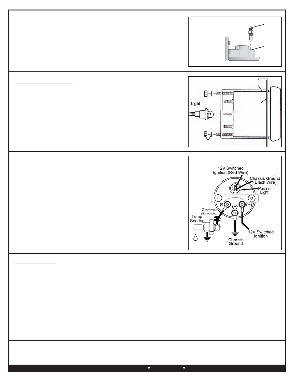
WIRING
(See Diagram #6)
1.
Connect an 18 gauge wire to the Temp Sender now mounted on the vehicle.
2.
Using a grommet (Not supplied) route the wire through the firewall and into
the passenger compartment where the Temperature Gauge is mounted.
3.
Attach the Temp Sender wire to the terminal marked (S) on the gauge.
4.
Attach an 18 gauge wire to the terminal marked (-) on the gauge, then attach
the other end of the wire with the black wire coming from the gauge light to a
suitable chassis ground.
5.
Attach an 18 gauge wire to the terminal marked (+) on the gauge, then attach
the other end of the wire with the red wire coming from the gauge light to a
12V Switched Ignition source.
Red Gauge Light wire can be connected to dash lights if desired.
Note:
TEMPERATURE SENDER INSTALLATION
Filter Mount Port Installation (See Diagram #4)
1.
Locate the port on the supplied Filter Mount.
2.
Using Teflon Tape or suitable sealant install the Temp Sender into the port on
the Filter Mount.
Warning: Installation of accessories should only be undertaken by those with mechanical knowledge and are familiar with working on
vehicles. Always use eye protection (goggles, safety glasses or shield). Park the vehicle in a well lit area, on level ground and apply the
parking brake. Only work on a cold vehicle that has been sitting overnight, failure to do so will result in severe burns and injury. Before starting
the vehicle, make sure no tools or any other items are left under hood that could interfere with or be drawn into moving parts of the engine.
Failure to follow instructions can lead to severe damage and personal injury.
Diagram #5
Gauge Mounting
Bracket
10-32 Mounting Nut & Washer
G
ge
Mounting
au
Bezel
Temperature
Gauge
GAUGE INSTALLATION
1.
Identify the best location for mounting the Temperature Gauge.
2.
Using the Gauge Mounting Bezel as a template, mark, drill and mount in the
proper location. (See Diagram #5)
3.
Install the Temperature Gauge into the Gauge Mounting Bezel. Using the
Gauge Mounting Bracket and 10-32 Mounting Nuts and Washers tighten the
Temperature Gauge into place.
SYSTEM CHECK
1.
Start the vehicle and quickly check all connections for leaks.
2.
With the vehicle in neutral, check the transmission fluid level.
3.
Add fluid as needed.
4.
Drive vehicle making sure transmission is warm, then recheck fluid level.
Temp Sender
Port
Diagram #4
Temp Sender
Diagram #6
Back View