3 load chain installation – R&M Materials Handling MANUAL CHAIN HOISTS User Manual
Page 17
RM SERIES II I&M MANUAL/EN/02.11.11
11/20
This document and the information contained herein, is the exclusive property of R&M Materials Handling, Inc., and represents a non-public, confidential and proprietary trade secret
that may not be reproduced, disclosed to third parties, altered or otherwise employed in any manner whatsoever without the express written consent of R&M Materials Handling, Inc.
Copyright © (2011) R&M Materials Handling, Inc. All rights reserved.
4.3
Load Chain Installation
1. Take a flexible wire of about 20 inches (50 cm) in length and insert the wire between the load wheel and
the chain guide until it comes out on the other side.
2. Hook the chain onto the end of the wire on the load side.
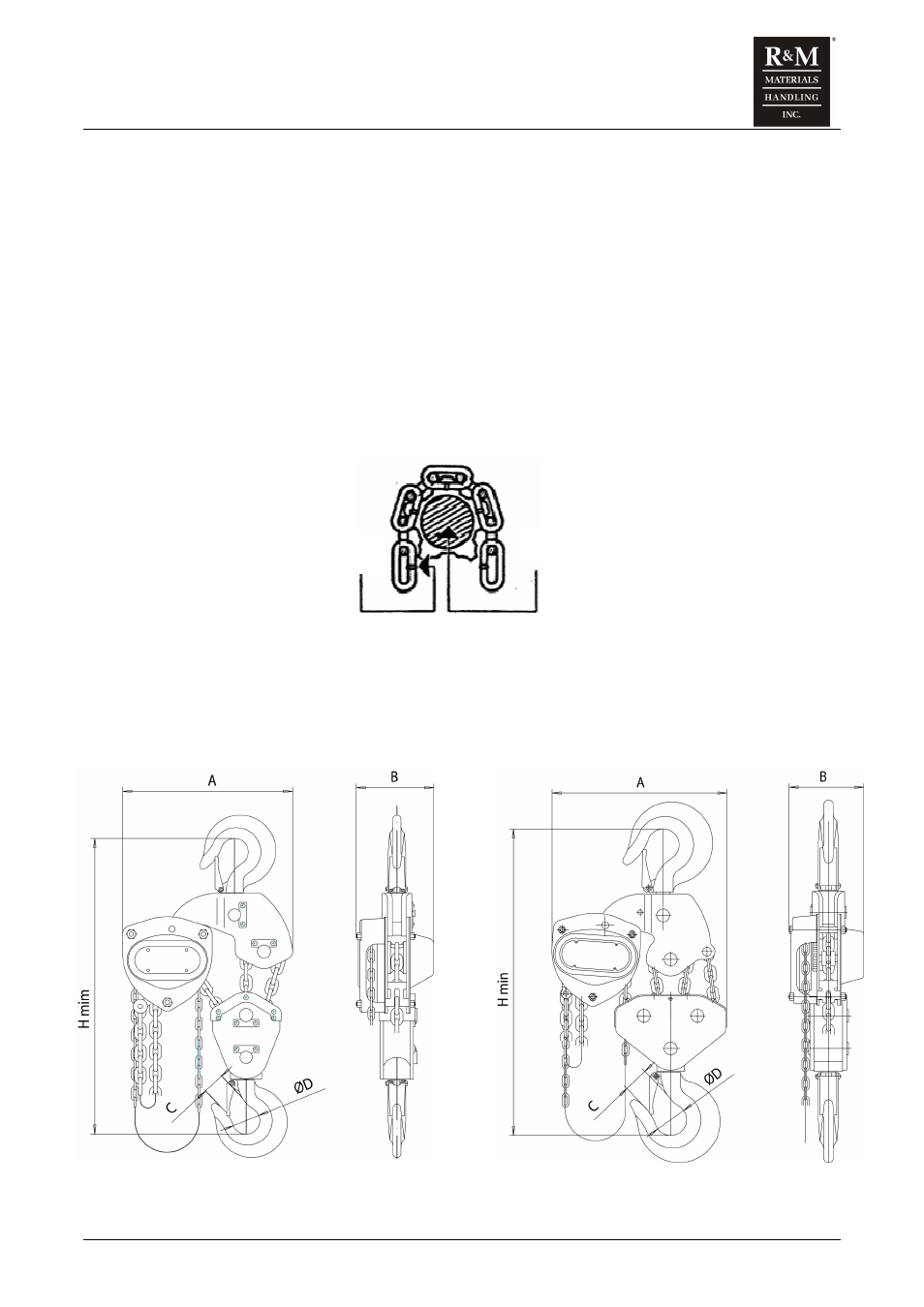
3. Pull the wire to bring the chain in contact with the load wheel while checking the position of the vertical
links. The link weld must be on the inside. (See figure)
4. Regulate the load chain tension.
5. Pull the hand chain.
6. Install the fall stop assembly. Fall stop assembly must be place at least 6” [150mm] from the free end of
the load chain.
Figure 2. Link Weld Orientation
Body Load Wheel
Link Weld
3 Fall Hoist
4 Fall Hoist