GE P&W Spiral Wound Membranes - Duraslick Series User Manual
Duraslick* series, Low fouling nf/ro elements, Fact sheet
Find a contact near you by visiting www.gewater.com and clicking on “Contact Us”.
* Trademark of General Electric Company; may be registered in one or more countries.
©2013, General Electric Company. All rights reserved.
FS1269EN.doc Nov-13
Fact Sheet
Duraslick* Series
Low Fouling NF/RO Elements
Duraslick
*
is a family series of membrane elements
engineered for use with fouling-prone brackish wa-
ter applications and industrial effluent treatment
before reuse or discharge. Duraslick* is designed to
utilize an innovative three-layer membrane, of
which a proprietary middle layer creates extreme
smoothness, and provide a high rejection of salts.
Independent studies have demonstrated that Du-
raslick* elements are superior to standard polyam-
ide spiral wound membrane elements for salt
removal in fouling environment. Duraslick* ele-
ments retrofit existing systems to obtain stable
permeate flux, reduced overall energy usage, in-
creased membrane service life and an extension of
operating time between required cleanings, which
in turn reduces expenditures on required chemicals.
Table 1: Element Specification
Membrane
Thin-film membrane (TFM*)
Model
Average
permeate flow
gpd (m3/day)
1,2
Average NaCl
rejection
1,2
Minimum NaCl
rejection
1,2
Duraslick RO2540
550 (2.1)
98.6%
97.0%
Duraslick RO4040
1,900 (7.2)
98.6%
97.0%
Duraslick RO8040
7,700 (29.1)
98.6%
97.0%
1
Average salt rejection after 24 hours operation. Individual flow rate may vary
+25%/-25%.
2
Testing conditions: 800ppm NaCl solution at 225psig (1,551 kPa) operating
pressure, 77°F (25°C), pH7.5 and 15% recovery.
Model
Average
permeate flow
gpd (m3/day)
1,2
Average
MgSO4
rejection
1,2
Minimum
MgSO4
rejection
1,2
Duraslick NF2540
600 (2.3)
98.6%
96.0%
Duraslick NF4040
2,400 (9.1)
98.6%
96.0%
Duraslick NF8040
8,600 (32.6)
98.6%
96.0%
1
Average salt rejection after 24 hours operation. Individual flow rate may vary
+25%/-25%.
2
Testing conditions: 2,000ppm MgSO
4
solution at 110psi (760kPa) operating
pressure, 77°F (25°C), pH7.5 and 15% recovery.
Model
Spacer
mil (mm)
Active area
ft
2
(m
2
)
Outer wrap
Part
number
Duraslick RO2540
30 (0.76)
24 (2.2)
Fiberglass
1231055
Duraslick RO4040
30 (0.76)
80 (7.4)
Fiberglass
1231048
Duraslick RO8040
30 (0.76)
355 (33.0)
Fiberglass
1231014
Duraslick NF2540
30 (0.76)
24 (2.2)
Fiberglass
1234385
Duraslick NF4040
30 (0.76)
80 (7.4)
Fiberglass
1234307
Duraslick NF8040
30 (0.76)
355 (33.0)
Fiberglass
1234182
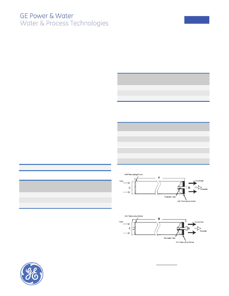
Figure 1: Element Dimensions Diagram – 8040
Figure 2: Element Dimensions Diagram – 2540 & 4040
Table 2: Dimensions and Weight