Operational description, Specifications – GE P&W IPER Integrated Pump and Energy Recovery User Manual
Page 2
Page 2
FSppIPER_EN
Operational Description
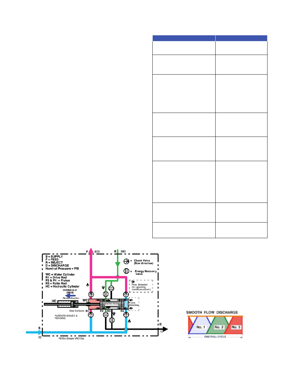
Figure 2 illustrates one of three double acting Wa-
ter Cylinders (WC), stroking to the left as noted, con-
sisting of Pumping Pistons (P2 & P4), separated by a
Ratio Rod (R3). The Pistons are powered by the
Hydraulic Cylinder (HC) in a trapezoidal wave form
(Figure 3) by means of a Drive Rod (R1).
Feed Pumping Function:
1. Supply pump flow enters at S, to the P4 piston.
2. Feed flow exits from the P2 piston to F to the
SWRO membranes.
Reject Energy Recovery Function:
1. High Pressure Reject returns from the SWRO
membranes to R, then through an Energy Re-
covery Valve to the back of Piston (P2), into the
smaller Piston area chamber determined by the
Ratio Rod.
2. The Reject pressure assists the Hydraulic Cylin-
der (HC) to create the Feed (F) pressure.
Reject Discharge Function:
1. Low Pressure Reject from a previous stroke ex-
ists from the chamber between R3 and P4.
2. This low pressure reject discharges through an
Energy Recovery Valve to D.
Complementary Action:
1. There are three double acting pressure strokes
resulting in six (6) power strokes per cycle. Each
of these pressure strokes have complementary
flow profiles as shown in the Trapezoidal Wave
Form diagram (Figure 3.)
2. For system flushing all of the Energy Recovery
Valves can be put in the open position, allowing
flow from S through F and R, then exiting at D,
without operating the Hydraulic Cylinders (HC)
or Water Cylinders (WC).
Specifications
ITEM DESCRIPTION
IPER-1000
Flow Range
Pressure Range
2,222 – 2,857 m
3
/day
10 - 80 bar
Water Cylinder material of con-
struction
Water Cylinder quantity
Water Cylinder orientation
Sch 40 Duplex 2205 Stain-
less Steel
3
Horizontal
Feed water valve style
Feed water valve material of
construction
Feed water valve quantity
Energy Recovery valve style
Energy Recovery valve material of
construction
Energy Recovery valve quantity
Single Direction Check
Zeron 100
12
Pilot Operated Check
Zeron 100
12
Hydraulic Cylinder Manufacturer
Hydraulic Cylinder Model
Hydraulic Cylinder quantity
Hydraulic Cylinder Max. Pressure
Milwaukee Hydraulic or
equal
H35D-MPV
3
206 bar
Hydraulic Pump Manufacturer
Hydraulic Pump Model
Hydraulic Pump quantity
Hydraulic Pump Max. Pressure
Hydraulic Pump reservoir size
Parker
Gold Cup P7R
3
206 bar
280 liters
Electronic control unit
manufacturer
Quantity
Controller
Interfaces with PLCs by:
Control Enclosure Material
Control Enclosure Rating
Control Power
GE
1
Solid state
GE, Allen Bradley, Siemens
FRP
IP 54
120 or 200 VAC, 1-phase,
50/60 Hz
Pressure Transmitter Manufacturer
Pressure Transmitter Model
Position Sensor Manfacturer
Position Sensor Model
Dwyer Instruments
626-15-GH-P1-E1-S1
MTS Temposonics
RHT0160UD601V2
Hydraulic Unit Dimensions (WXDXH)
Water Displacement Unit
Dimensions (WXDXH)
260 x 290 x 740 cm
260 x 290 x 740 cm
Figure 2: IPER Function
Figure 3: IPER smooth flow discharge