Desktop mounting surface lock down installation 1, Figure. 1.1, Gb fig 1.2 – Peerless-AV GC-WII - Installation User Manual
Page 7
7 of 7
ISSUED: 1-17-11 SHEET #: 125-9179-2 07-31-12
Desktop Mounting Surface Lock down Installation
1
© 2011 Peerless Industries, Inc. All rights reserved.
Peerless is a registered trademark of Peerless Industries, Inc. Other parties’ marks are the property of their respective owners.
Figure. 1.1
Wii™
TOP OF MOUNTING SUrFAce
B
J
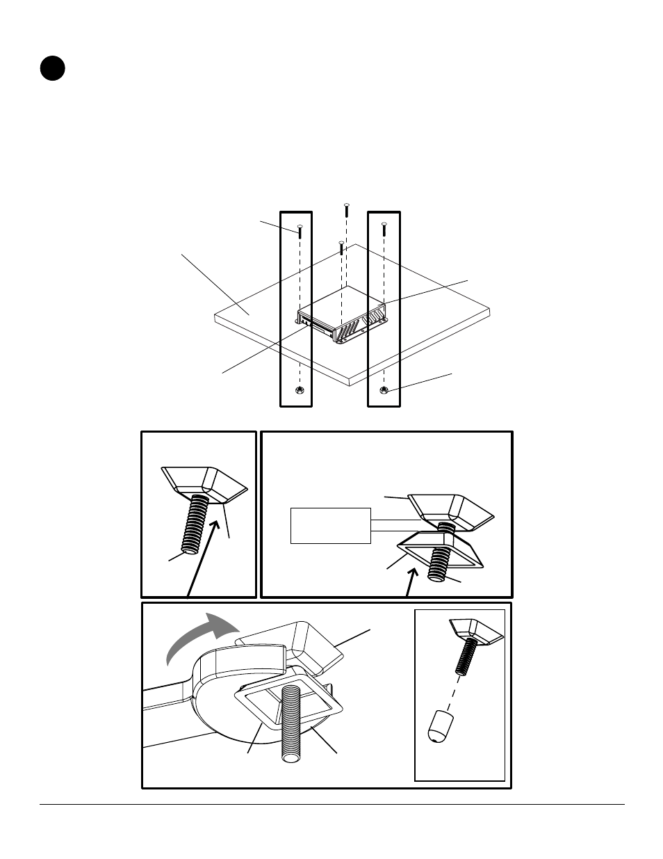
Place lock down plate (
A) onto mounting surface as a template. Level, and mark the center of four rectangular
mounting holes. Drill four 5/16” (8 mm) dia. holes through desktop mounting surface. Secure using four carriage
bolts (
B) though lock down plate (A) and mounting surface as shown in figure 1.1.
Secure two 1/4-20 x 1 3/4” carriage bolts (
B) using two 1/4-20 nylock nuts (J) in corners as shown in figure 1.1.
Using remaining 1/4-20 x 1 3/4” carriage bolts (
B), hand tighten slope nut (F) through 1/4-20 x 1 3/4" carriage bolt
(
B) until snug against bottom of desktop surface as shown in figure detail 1 Thread another slope nut (F) upside-
down, about two turns from first slope nut (
F) as shown in detail 2. Insert a open box wrench between both slope
nuts (
F) and tighten as shown in detail 3.
NOTE: Avoid jamming both slope nuts (F) together, doing so may make it difficult to remove slope nut used for
tightening first slope nut (
F) as shown in figure 1.3. After slope nut is secure remove bottom slope nut and add
plastic cap (
G) as shown in figure 1.2. repeat with remaining 1/4-20 x 1 3/4" carriage bolt (B).
G
B
FIG 1.2
Detail 3
TIGHTENING
SLOPE NUT (F)
F
5/8" OPEN BOX
WRENCH
TIGHTENING
SLOPE NUT (F)
B
B
F
Detail 1
Detail 2
F
BOTTOM OF DESK
BOTTOM OF DESK
NOTE: Avoid jamming both slope nuts (G) together,
doing so may make it difficult to remove slope nut
used for tightening.
After slope nut is secure remove bottom slope nut.
LEAVE SPACE
IN BETWEEN
SLOPE NUTS
A