Fi g 4.1 fi g 4.2 – Peerless-AV ACC951 - Installation User Manual
Page 3
ISSUED: 10-31-10 SHEET #: 120-9091-2 11-08-10
Visit the Peerless Web Site at www.peerlessmounts.com
For customer care call 1-800-729-0307 or 708-865-8870.
3 of 3
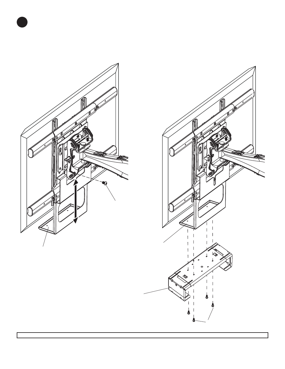
Insert two M10 x 15 mm socket screws into bottom mounting holes of adapter plate as shown in fi gure 4.1.
Adjust accessory bracket (A) so bottom tray touches bottom of display and tighten all fasteners using a 6 mm
allen wrench included with wall arm.
Attach DS or VPM component shelf (sold separately) to bottom tray using M5 screws included with DS or VPM
component shelf as shown in fi gure 4.2.
4
© 2010, Peerless Industries, Inc. All rights reserved.
All other brand and product names are trademarks or registered trademarks of their respective owners.
BOTTOM TRAY
BOTTOM TRAY
M10 X 15 MM SCREWS
M5 SCREWS
fi g 4.1
fi g 4.2
DS OR VPM COMPONENT
SHELF (SOLD SEPARATELY)
- WBK100-W - Installation (3 pages)
- ACC800 - Installation (1 page)
- PLP-V8X4 - Installation (1 page)
- ACC244 - Installation (2 pages)
- ACC952 - Installation (20 pages)
- MOD-CPI - Sell Sheet (2 pages)
- ACC-M8RI - Sell Sheet (2 pages)
- DS496 - Installation (8 pages)
- ACC615 - Installation (2 pages)
- WSP724-W - Sell Sheet (2 pages)
- GC-UNV - Installation (13 pages)
- PE1120-W - Sell Sheet (2 pages)
- FLD-UNV-S - Sell Sheet (2 pages)
- PB-1 - Sell Sheet (2 pages)
- MOD-APC - Installation (8 pages)
- PAP-UNV-W - Installation (1 page)
- PAP-UNV-W - Installation (2 pages)
- CL-SCG200 - Sell Sheet (1 page)
- ACC325 - Installation (2 pages)
- PLP-V3X3 - Installation (1 page)
- VPM25-J - Installation (5 pages)
- ACC912 - Installation (5 pages)
- ACC002 - Sell Sheet (2 pages)
- PLP-V6X2 - Installation (1 page)
- DCT100 - Installation (2 pages)
- CMJ471 - Installation (2 pages)
- EXT series 1 - Installation (1 page)
- ACC952 - Sell Sheet (2 pages)
- ACC-SB - Sell Sheet (2 pages)
- ACC330 - Installation (3 pages)
- PLP-V4X3 - Installation (1 page)
- ACC908 - Installation (5 pages)
- DCT500 - Installation (1 page)
- CMJ450 - Installation (4 pages)
- AEC1012_S_W - Sell Sheet (2 pages)
- DSF290 - Installation (12 pages)
- ACC604 - Installation (6 pages)
- ACC111 - Installation (1 page)
- DS334 - Installation (4 pages)
- PLP-V2X1 - Installation (1 page)
- ACC560 - Installation (4 pages)
- WSP820 - Installation (2 pages)
- FLD-UNV-S - Installation (3 pages)
- ACC-EXC - Installation (2 pages)