I3 memory locations – B&B Electronics I3A12X_20B05-SOHF - Manual User Manual
Page 4
Basic Operation
3
i Memory Locations
Type
Description and example of what might use the type
Format
%I
Discrete Inputs from the field; proximity sensors, panel
buttons, etc
BOOL
%Q
Discrete Outputs to the field; relays, indicator lamps,
etc.
BOOL
%AI
Analogue Inputs from the field; Thermocouples,
WORD
4-20mA inputs
%AQ
Analogue Outputs to the field; 0-10VDC or 4-20mA
outputs
WORD
%IG
Global Discrete Inputs from the CAN smart I/O;
BOOL
%QG
Global Discrete Outputs to the CAN smart I/O;
BOOL
%AIG
Global Analogue Inputs from the CAN smart I/O;
WORD
%AQG
Global Analogue Outputs to the CAN smart I/O;
WORD
%T
Internal Temporary bits, use for contacts and coils
BOOL
%M
Internal Memory bits, use for contacts and coils
BOOL
%R
Internal Registers, use for timers, counters & other data
WORD
%K
Keypad bits, reflect Function Key status
BOOL
%D
Display bits, control screens or indicate screen on/off
BOOL
%S
Internal System Bits (See System Registers)
BOOL
%SR
Internal System Registers (See System Registers)
WORD
Note: The allocation of I/O starts from 1 the first input is %*01 and not %*00
.
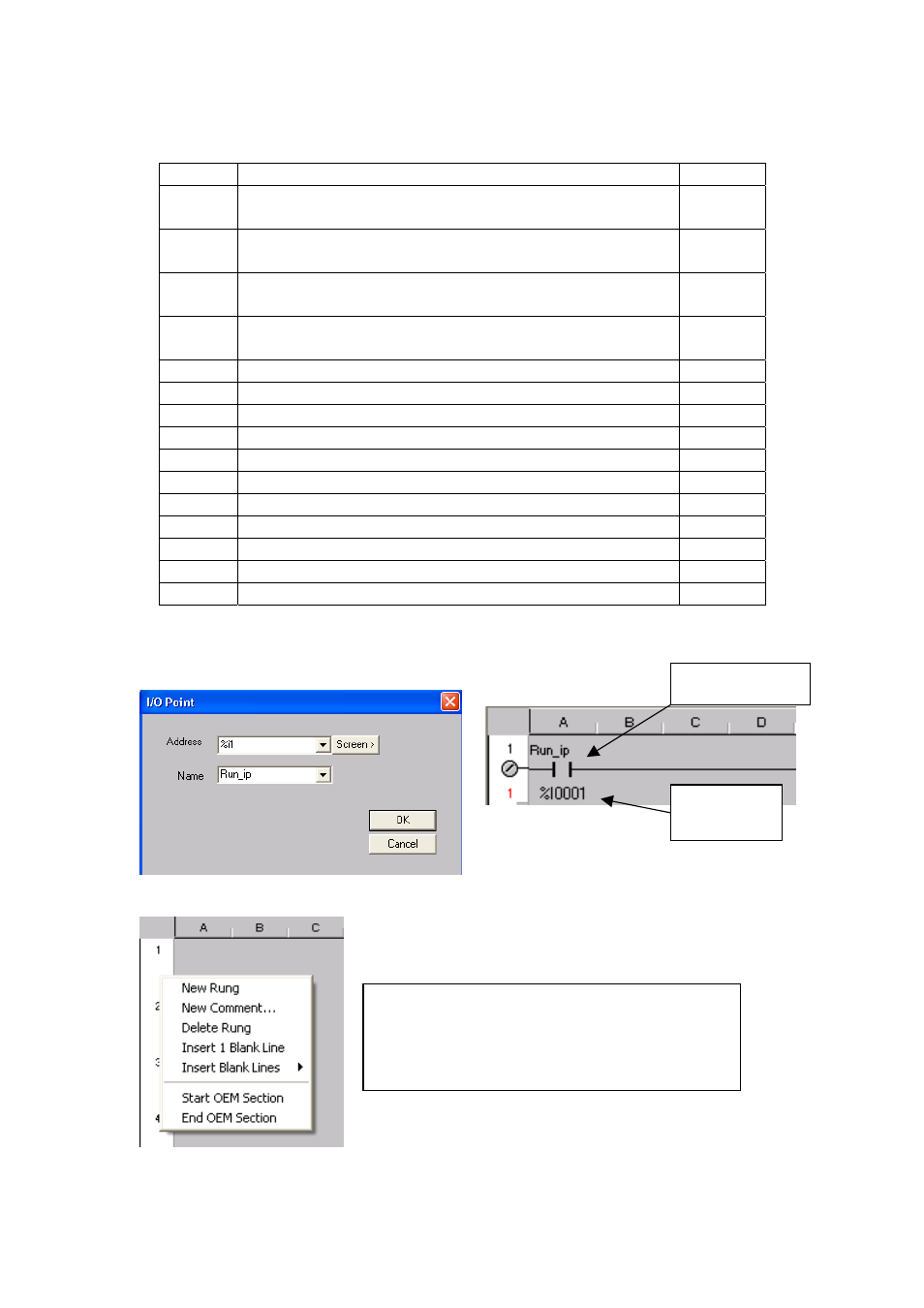
Contact name
Contact
address
By right clicking the mouse in the left margin
we can have some more options.
We have the options to add or remove rungs,
insert documentation and start OEM sections.
© IMO Precision Controls ltd.
5