Connecting the vesr321, Fiber optic connection – B&B Electronics VESR321_ML_SL - Manual User Manual
Page 12
Setup and Connections
www.bb-elec.com
www.bb-europe.com
8
When configured for 2-wire (half duplex) operation the connection supports one signal pair:
Data A (-) and Data B (+). The data lines are differential with the Data B line positive relative to
Data A in the idle (mark) state. Ground provides a common mode reference.
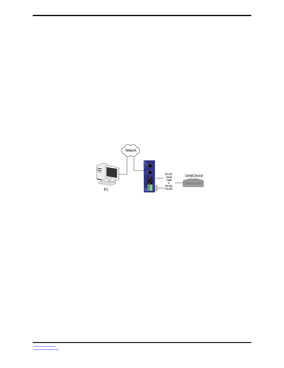
Connecting the VESR321
VESR321 serial servers feature one DB9M connector for RS-232 and a five-position removable
terminal block for RS-422 and RS-485 connections.
If you select RS-232 mode when you configure the serial server, you must connect the serial
device to the serial server via a serial cable. The VESR321 is a DTE. If the serial device is a DTE,
use a null modem (cross-over) cable. If the serial device is a DCE, use a straight-through cable.
If you select RS-422 mode, RS-485 2-wire mode, or RS-485 4-wire mode when you configure the
serial server, you must connect the serial device appropriately, via the 5-position terminal block.
Note: Refer to Appendix D for connector pinout information.
Figure 9. VESR321 Family Connections
Connecting VESR321 Serial Servers to a Network
Network Connection (10BaseT/100BaseTX)
When connecting a serial server equipped with a 10BaseT/100BaseTX network connection
(RJ45 connector) a standard network cable is connected from the serial server to a network drop.
PCs configuring and/or communicating with the serial server are also connected to the network.
Fiber Optic Connection
When connecting a serial server equipped with a fiber optic interface to a fiber optic link
the appropriate fiber optic cable must be connected between the serial server and the network
interface. Refer to the list of VESR321 family serial server models at the beginning of this manual
for a list of supported fiber types and distances.