Rs-485 mode – B&B Electronics ESP904 - Manual User Manual
Page 21
Making Hardware Connections
Manual Documentation Number: ESP904-4513m
Chapter 2
11
B&B Electronics Mfg Co Inc – 707 Dayton Rd - PO Box 1040 - Ottawa IL 61350 - Ph 815-433-5100 - Fax 815-433-5104 – www.bb-elec.com
B&B Electronics Ltd – Westlink Commercial Park – Oranmore, Galway, Ireland – Ph +353 91-792444 – Fax +353 91-792445 – www.bb-europe.com
N
N
o
o
t
t
e
e
:
:
Refer to Appendix B RS-422 connection pin-outs.
RS-485 Mode
In
RS-485 Mode
Mode
the currently selected serial port is configured as an
RS-485 interface supporting transmit (TX) and receive (RX) signal channels
using 2-wire, half-duplex operation. The data lines are differential with the
Data B line positive relative to Data A in the idle (mark) state. Ground
provides a common mode reference.
N
N
o
o
t
t
e
e
:
:
Refer to Appendix C for RS-485 connection pin-outs.
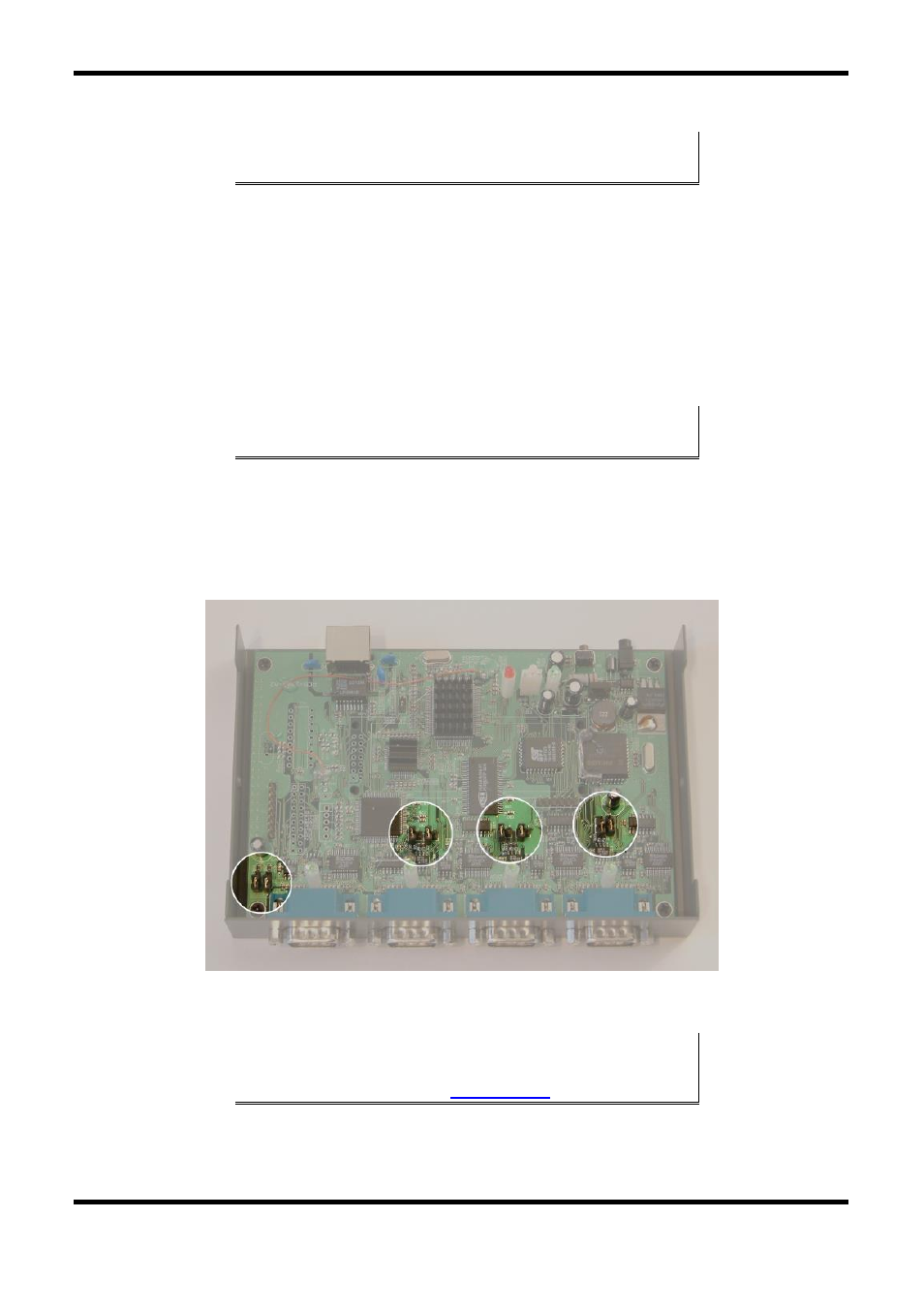
RS-485 Receiver Biasing
can be implemented from the ESP904 if the
network does not supply it. Remove the two side-cover screws of the
ESP904, slide the cover off and re-position the bias jumpers (shown open in
the figure below) to enable biasing (shorting).
Figure 6. Internal Setting to Select RS-485 Bias
N
N
o
o
t
t
e
e
:
:
(For more information on RS-485 Receiver Biasing, see B&B Electronics RS-
422/485 Application Note available a