Configuring the isocon – B&B Electronics ISOCON-6 - Manual User Manual
Page 5
ISOCON-6 USERS GUIDE
4. CONFIGURING THE ISOCON
!
! WARNING !
DO NOT OPEN UNIT OR ADJUST SWITCHES WITH
POWER SUPPLY, INPUT OR OUTPUT CONNECTED
The ISOCON is an extremely versatile device which can support many different
types of input. The unit is configured by turning the power off, selecting the
internal switch settings required and turning the power back on.
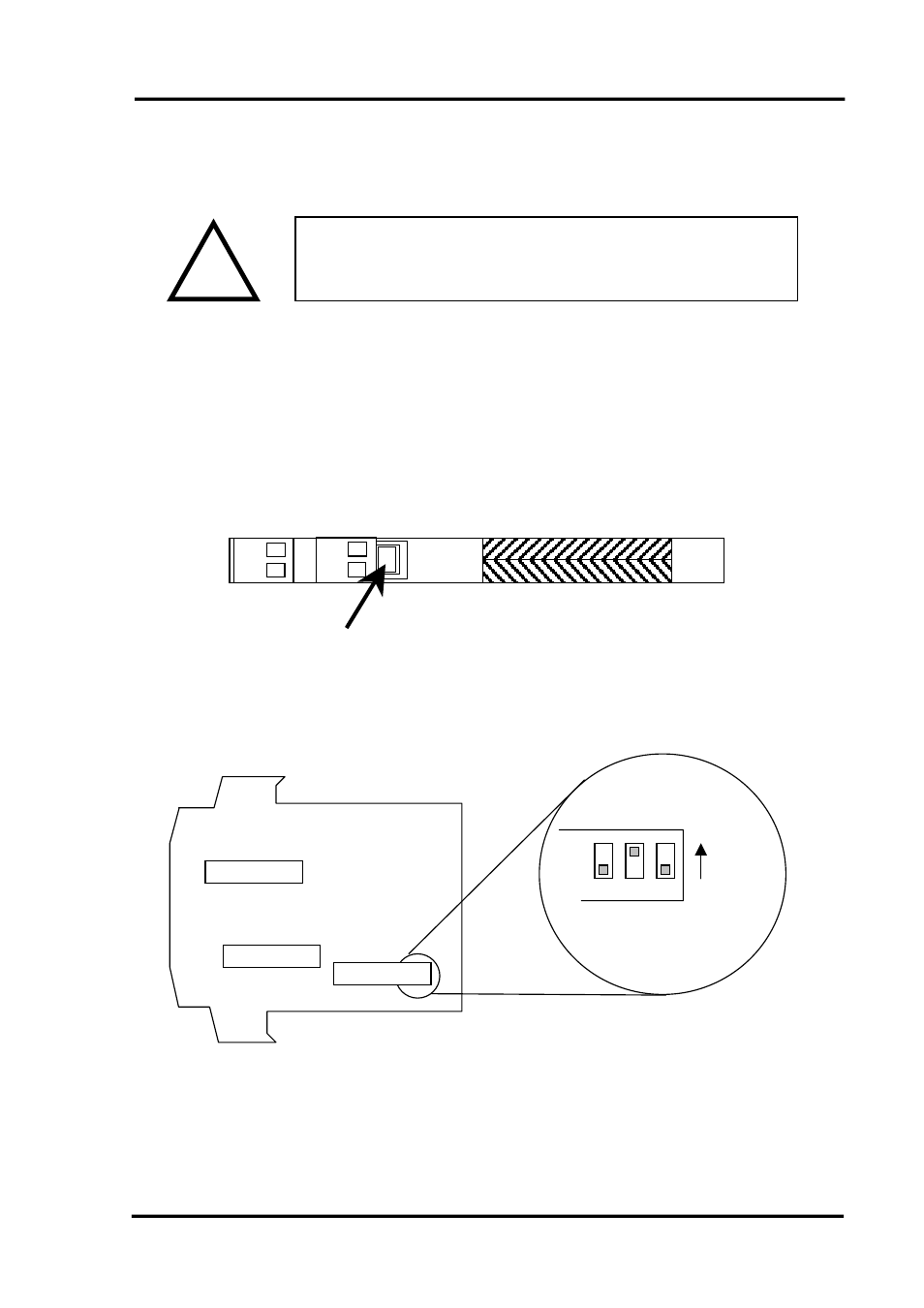
To open the Isocon, 2 catches just below the outer terminal blocks must be pushed
in gently, one at a time. The front of the case can then be pulled and the unit will
come out of the box.
Press here gently
There are 3 switch banks, S1, S2, and S3, located inside the ISOCON as shown
below:
Switch 10 is OFF
Switch 11 is ON
Switch 12 is OFF
OFF = 0
ON = 1
12
11
10
Switch S3
12
1
Switch S1
Switch S2
12
12
1
1
Switch S1 and S2 configure the input type and range, and switch S3 configures the
output type, range and a few additional functions. The switch settings are explained
in the next few pages. The diagrams refer to switch positions 0 and 1, with 0 being
OFF and 1 being ON. This is illustrated in the picture above.
IIG-010801 Page
5