Output configuration, 7 output, Configuration – B&B Electronics ISOCON-6 - Manual User Manual
Page 12: Examples
ISOCON-6 USERS GUIDE
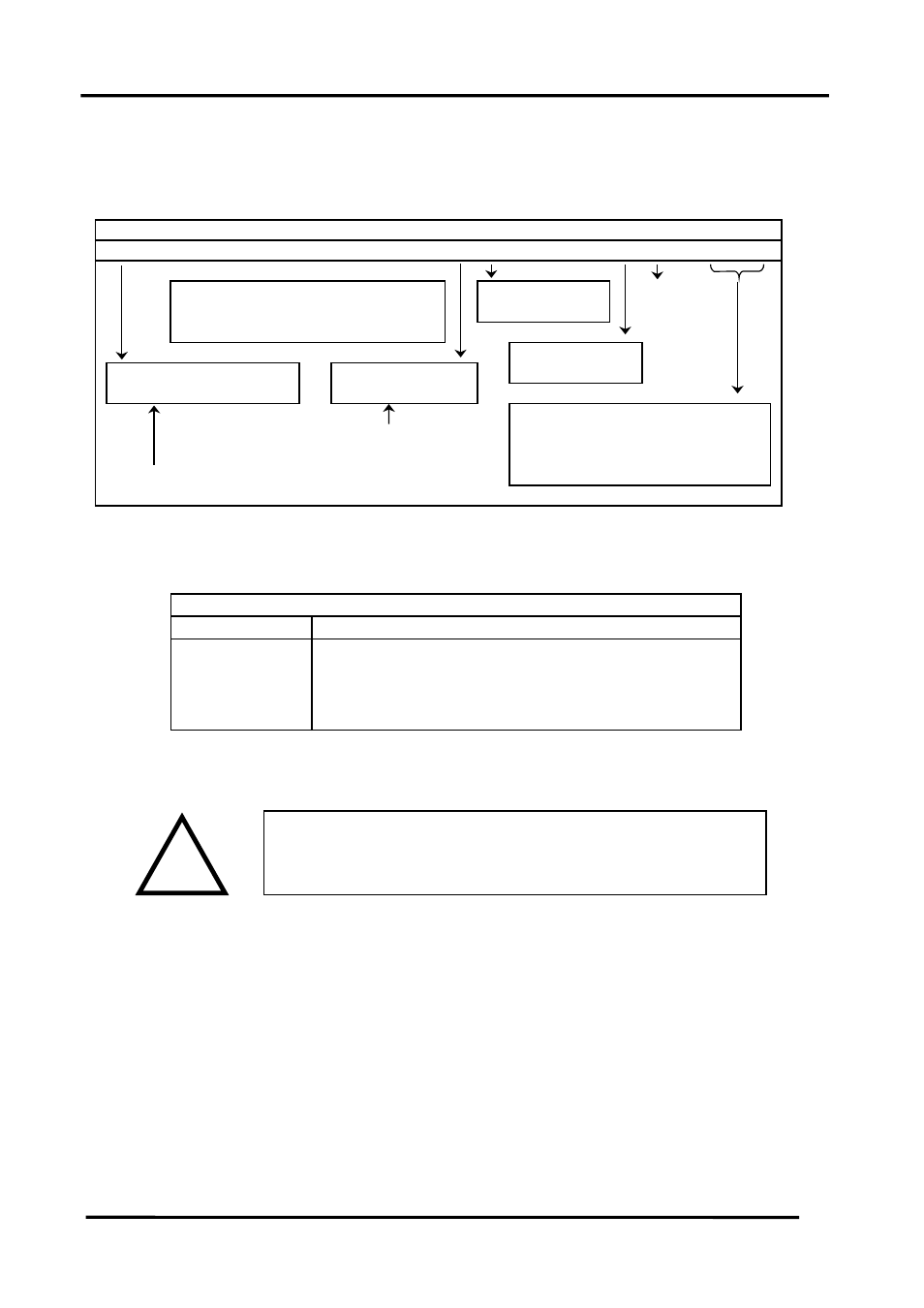
4.1.7 Output Configuration
Select the range from the table below and set Switch S3 to the required values.
1
2
3
4
5
6
7
8
9
10
11 12
0
1
0
1
0 mA Source
0 Normal
0
1
0
1
0
0 mA Sink
1 Inverted o/p
0
1
0
1
1 Voltage
Normal 0
0 Buttons Disabled
High Burnout 0
Square Root 1
1 Buttons Enabled
Low Burnout 1
4-20mA / 2-10V
0
0
Output value if fault on input signal
0-20mA / 0-10V
0
1
0-10mA / 0-5V
1
0
Front panel buttons can be disabled to allow
2-10mA / 1-5V
1
1
tamper-proof operation of unit
Switch S3 - Output Configuration
Examples:
1
2
3
4
5
6
7
8
9
10 11 12
4-20mA Source
1
0
1
0
1
0
0
0
0
0
0
0
0-20mA Source
1
0
1
0
1
0
0
0
0
0
0
1
0-10V
1
0
1
0
1
1
0
0
0
0
0
1
4-20mA Sink
1
1
0
1
0
0
0
0
0
0
0
0
Switch S3 Examples
!
! WARNING !
DO NOT OPEN UNIT OR ADJUST SWITCHES WITH
POWER SUPPLY, INPUT OR OUTPUT CONNECTED
Please note that PC Software is available to provide information on
switch settings for your input and output requirements.
Page
12
IIG-010801
- USOPTL4DR-LS - Datasheet (2 pages)
- ZXT9-IOA-KIT - Manual (75 pages)
- ADAM-6066 - Manual (272 pages)
- 855-11619--57 - Datasheet (2 pages)
- 851-10904 - Datasheet (2 pages)
- SS-BLT-100PR - Quick Start Guide (1 page)
- ISOCON-6 - Datasheet (2 pages)
- I-7060 - Manual (64 pages)
- AMU864 - Datasheet (2 pages)
- 714FX6-SC_ST - Manual (154 pages)
- 422LP25R - Datasheet (2 pages)
- ZP9D-115RM-LR - Manual (54 pages)
- EKI-6311GN-EU - Manual (56 pages)
- ZZ24D-NA(NB,NC,ND)-SR - Quick Start Guide (4 pages)
- ESCLP-100 - Manual (23 pages)
- 806-39753 - Datasheet (1 page)
- 485SD9RJ - Datasheet (1 page)
- 712FX4-SC_ST - Manual (154 pages)
- 850-18610 - Manual (18 pages)
- ESW208 Series - Datasheet (2 pages)
- VESR321_ML_SL - Quick Start Guide (3 pages)
- OP10 - Datasheet (1 page)
- RT3G-300_310_320_330_340-W - Configuration Manual (79 pages)
- EIRHP305-T - Datasheet (2 pages)
- EIRSP1 - Datasheet (1 page)
- 422TTL33 - Datasheet (2 pages)
- 485DRCI - Quick Start Guide (2 pages)
- I-7021_P - Datasheet (2 pages)
- NTSA-CAT5E - Datasheet (2 pages)
- 485COSR - Datasheet (2 pages)
- 855-10619--57 - Datasheet (2 pages)
- UH401SL_2KV - Datasheet (2 pages)
- 105FXE-SC(ST)-15-POE - Manual (19 pages)
- 102MC-FL_SC_ST - Manual (23 pages)
- CBL00302 - Datasheet (1 page)
- 850-18100--27 - Datasheet (2 pages)
- 850-10953-DC - Datasheet (2 pages)
- ESR904 - Datasheet (2 pages)
- 308TX-N - Datasheet (3 pages)
- 422LP25N - Datasheet (2 pages)
- 708FX2-SC_ST - Datasheet (3 pages)
- MESR321_SL_ML - Datasheet (2 pages)
- SL2736-698 - Quick Start Guide (8 pages)
- I-7188E Series - Datasheet (1 page)
- ANT-PAD58-19 - Datasheet (1 page)