Troubleshooting, Incorrect reading, Sensor failure – B&B Electronics ISOCON-6 - Manual User Manual
Page 15: Troubleshooting 7.1 incorrect, Reading, 2 sensor, Failure
ISOCON-6 USERS GUIDE
7. TROUBLESHOOTING
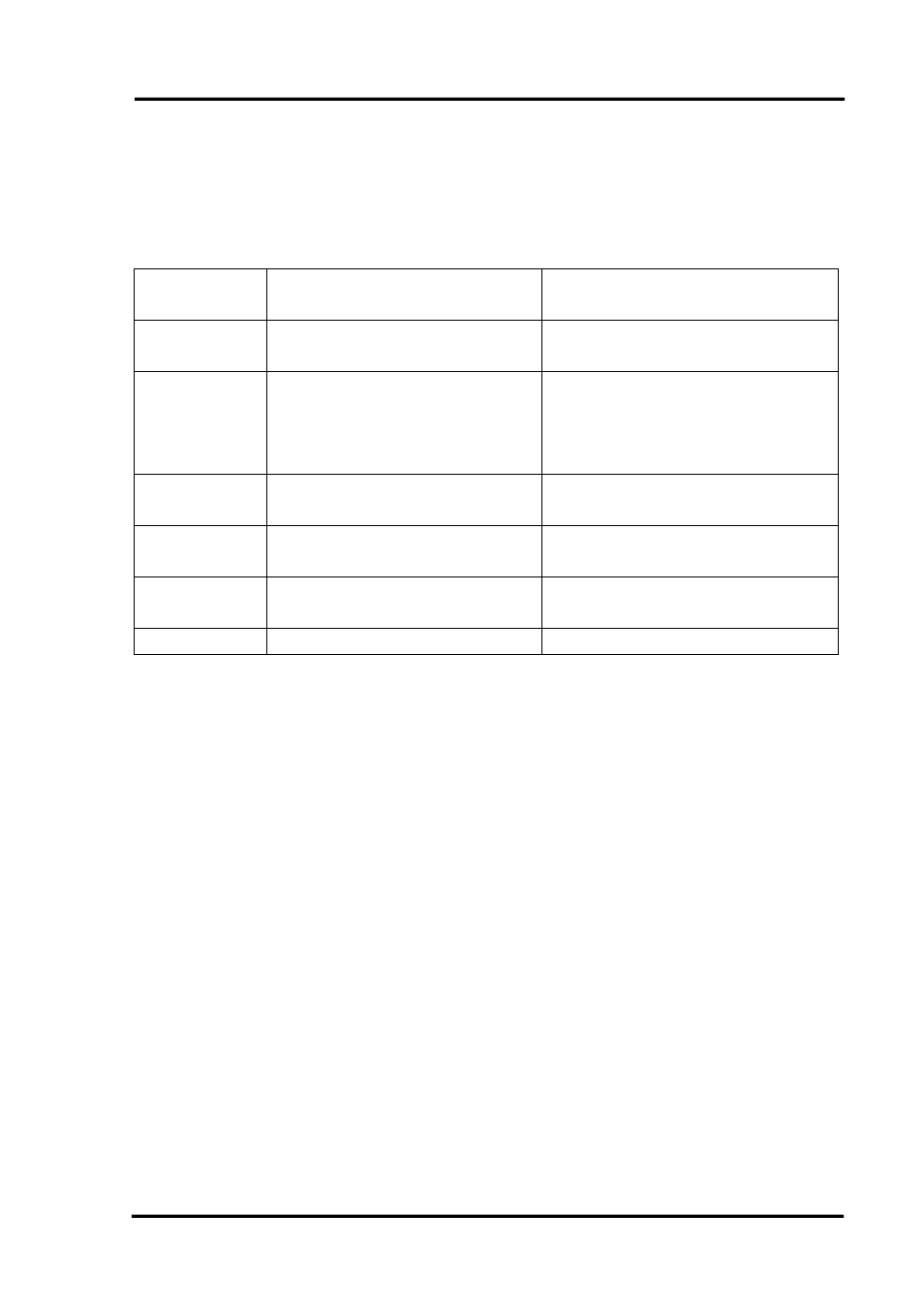
The ISOCON has some built in self diagnostic functions. If the LED on the front
panel is flashing then the fault mode can be found by counting the number of flashes
between gaps and using the table below to locate the problem.
No of
Flashes
Nature of Fault
Corrective Action
0
(Green On)
Unit Working – no suspected
fault
Check Wiring and switch
settings
2,3,4,5,6,8,9,
10,11,12
Green
Hardware Error, extreme
noise, poor supply
Switch off unit, check switch
settings, and wiring, and retry.
If still faulty please contact
supplier
7
Green RTD / Thermocouple
burnout
Repair RTD, T/C or wiring
3 or 4 Red Span point is too close to
zero point
Change input span value and
retry
3 or 4
Yellow
Zero point is too close to
span point
Change input zero value and
retry
No LED
Power Failure
Check supply lines and voltage
7.1 Incorrect Reading
•
Check that Unit is configured for the correct Sensor
•
Check that Input Scaling is as required.
•
Check that Linearisation has not been set incorrectly.
•
Check that Thermocouples have correct compensation cables, and polarity.
•
Check that RTD is set for correct option 2, 3 or 4 Wire.
•
Check that RTD leads are connected to appropriate terminal pins.
7.2 Sensor Failure
•
Check that sensor wiring is correct.
•
Check Thermocouple polarity.
•
Check that all RTD leads are connected to correct terminals.
•
Check that the ISOCON is configured for correct sensor.
•
Check that applied voltage is not out of range.
•
Check that applied current is not out of range.
•
Check that applied millivoltage is out of range.
IIG-010801 Page
15