Absolute maximum ratings, Dc electrical characteristics, Max3107 spi/i – Rainbow Electronics MAX3107 User Manual
Page 6: C uart with 128-word fifos and internal oscillator
6 ______________________________________________________________________________________
MAX3107
SPI/I
2
C UART with 128-Word FIFOs
and Internal Oscillator
Stresses beyond those listed under “Absolute Maximum Ratings” may cause permanent damage to the device. These are stress ratings only, and functional
operation of the device at these or any other conditions beyond those indicated in the operational sections of the specifications is not implied. Exposure to absolute
maximum rating conditions for extended periods may affect device reliability.
(Voltages referenced to AGND.)
V
L
, V
A
, V
EXT
, XIN ................................................ -0.3V to +4.0V
V
18
, XOUT .................................................. -0.3V to (V
A
+ 0.3V)
RST, IRQ, DIN/A1, CS/A0, SCLK/SCL,
DOUT/SDA, LDOEN, I
2
C/SPI .................. -0.3V to (V
L
+ 0.3V)
TX, RX, RTS/CLKOUT, CTS, GPIO_ ....... -0.3V to (V
EXT
+ 0.3V)
DGND .................................................................. -0.3V to +0.3V
Continuous Power Dissipation (T
A
= +70NC)
24-Pin TQFN (derate 15.4mW/NC above +70NC) ...... 1229mW
24-Pin SSOP (derate 12.3mW/NC above +70NC) ........ 988mW
Junction-to-Ambient Thermal Resistance (B
JA
) (Note 1)
24-Pin TQFN ............................................................. +65NC/W
24-Pin SSOP ............................................................. +81NC/W
Junction-to-Case Thermal Resistance (B
JC
) (Note 1)
24-Pin TQFN .............................................................. +15NC/W
24-Pin SSOP ............................................................. +32NC/W
Operating Temperature Range ........................ -40NC to +85NC
Junction Temperature ................................................... +150NC
Storage Temperature Range ........................... -65NC to +150NC
Lead Temperature (soldering, 10s) ................................+300NC
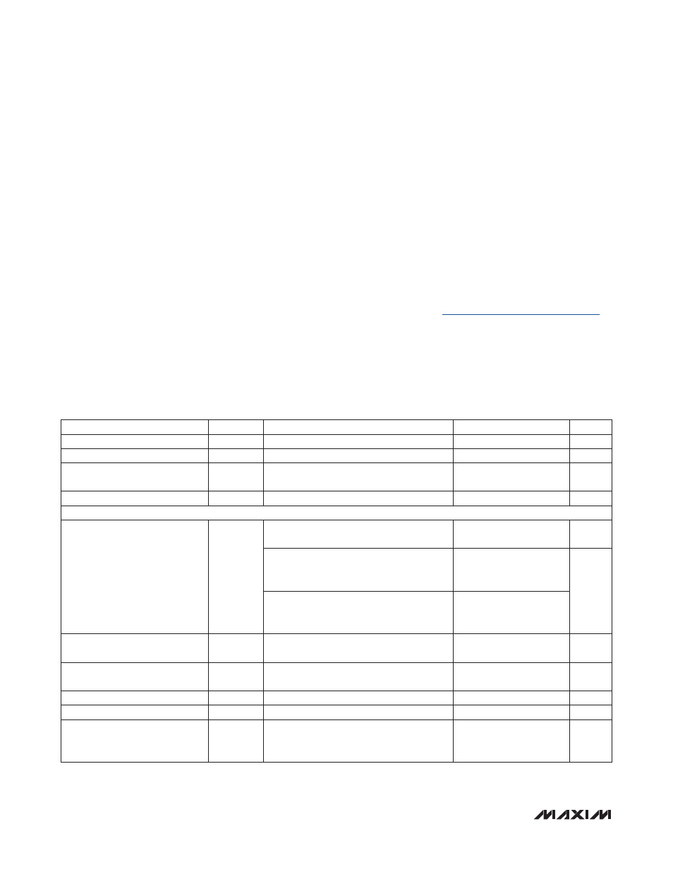
DC ELECTRICAL CHARACTERISTICS
(V
A
= +2.35V to +3.6V, V
L
= +1.71V to +3.6V, V
EXT
= +1.71V to +3.6V, T
A
= -40NC to +85NC, unless otherwise noted. Typical values
are at V
A
= +2.8V, V
L
= +1.8V, V
EXT
= +2.5V, T
A
= +25NC.) (Note 2)
ABSOLUTE MAXIMUM RATINGS
Note 1: Package thermal resistances were obtained using the method described in JEDEC specification JESD51-7, using a four-
layer board. For detailed information on package thermal considerations, refer to
.
PARAMETER
SYMBOL
CONDITIONS
MIN
TYP
MAX
UNITS
Digital Interface Supply Voltage
V
L
1.71
3.6
V
Analog Supply Voltage
V
A
2.35
3.6
V
UART Interface Logic Supply
Voltage
V
EXT
1.71
3.6
V
Logic Supply Voltage
V
18
1.65
1.80
1.95
V
CURRENT CONSUMPTION
V
A
Supply Current
I
A
1.8MHz crystal oscillator active, PLL dis-
abled, V
LDOEN
= V
L,
SPI/I
2
C interface idle
220
500
F
A
Baud rate = 1Mbps, external clock, SPI
frequency is 8MHz, external loopback PLL
disabled, V
LDOEN
= V
L
(Note 3)
0.65
1.3
mA
Internal oscillator enabled, PLL = 6X,
TX-RX loopback, continuous data transmis-
sion at 115kbps, V
LDOEN
= V
L
(Note 3)
4
8
V
A
Shutdown Supply Current
I
A, SHDN
Shutdown mode, V
LDOEN
= 0V, V
RST
= 0V,
all inputs and outputs are idle
20
35
F
A
V
A
Sleep Supply Current
I
A, SLEEP
Sleep mode, V
LDOEN
= V
L
, V
RST
= V
L,
all
inputs and outputs are idle
45
100
F
A
V
L
Supply Current
I
L
All logic inputs are at V
L
or V
EXT
or 0V
4
15
F
A
V
EXT
Supply Current
I
EXT
All logic inputs are at V
L
or V
EXT
or 0V
5
10
F
A
V
18
Input Power-Supply Current
in Shutdown Mode
I
18SHDN
V
LDOEN
= 0V (V
18
is powered by an exter-
nal 1.85V voltage source), static power
consumption
7
50
F
A