Max3107 spi/i, C uart with 128-word fifos and internal oscillator, Pin descriptions (continued) – Rainbow Electronics MAX3107 User Manual
Page 13
______________________________________________________________________________________ 13
MAX3107
SPI/I
2
C UART with 128-Word FIFOs
and Internal Oscillator
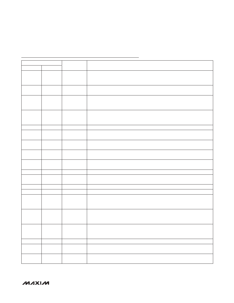
Pin Descriptions (continued)
PIN
NAME
FUNCTION
TQFN-EP
SSOP
7
10
DIN/A1
Serial-Data and Address 1 Input. When I2C/SPI is high, DIN/A1 functions as the DIN
SPI serial-data input. When I2C/SPI is low, DIN/A1 functions as the A1 I
2
C device
address programming input and connects to DIN/A1 DGND or V
L
.
8
11
IRQ
Active-Low Interrupt Open-Drain Output. IRQ is asserted when an interrupt is
pending.
9
12
RST
Active-Low Reset Input. Drive RST low to force the UART into hardware reset mode.
In hardware reset mode, the oscillator and the internal PLL are shut down; there is
no clock activity.
10
13
V
L
Digital Interface Logic-Level Supply. V
L
powers the internal logic-level translators for
RST, IRQ, DIN/A1, CS/A0, SCLK/SCL, DOUT/SDA, LDOEN, and I2C/SPI. Bypass V
L
with a 0.1FF ceramic capacitor to DGND.
11
14
DGND
Digital Ground
12
15
GPIO0
General-Purpose Input/Output 0. GPIO0 is user programmable as an input or output
(push-pull or open drain). GPIO0 has a weak pulldown resistor to ground.
13
16
GPIO1
General-Purpose Input/Output 1. GPIO1 is user programmable as an input or output
(push-pull or open drain). GPIO1 has a weak pulldown resistor to ground.
14
17
GPIO2
General-Purpose Input/Output 2. GPIO2 is user programmable as an input or output
(push-pull or open drain). GPIO2 has a weak pulldown resistor to ground.
15
18
GPIO3
General-Purpose Input/Output 3. GPIO3 is user programmable as an input or output
(push-pull or open drain). GPIO3 has a weak pulldown resistor to ground.
16
19
CTS
Active-Low Clear-to-Send Input. CTS is a flow-control input.
17
20
RTS/CLKOUT
Active-Low Request-to-Send Output. RTS/CLKOUT can be set high or low by pro-
gramming bit 7 (RTS) of the LCR register.
18
21
RX
Receive Input. Serial UART data input. RX has an internal weak pullup resistor to V
EXT
.
19
22
TX
Transmit Output. Serial UART data output.
20
23
V
EXT
Transceiver Interface Level Supply. V
EXT
powers the internal logic-level translators
for RX, TX, RTS, CTS, and GPIO_. Bypass V
EXT
with a 0.1FF ceramic capacitor to
DGND.
21
24
XOUT
Crystal Output. When using an external crystal, connect one end of the crystal to
XOUT and the other to XIN. When using an external clock source or the internal
oscillator, leave XOUT unconnected.
22
1
XIN
Crystal/Clock Input. When using an external crystal, connect one end of the crystal
to XIN and the other one to XOUT. When using an external clock source, drive XIN
with the external clock. When using the internal oscillator, leave XIN unconnected.
23
2
AGND
Analog Ground
24
3
V
A
Analog Supply. V
A
powers the internal oscillators, PLL, and internal LDO. Bypass
V
A
with a 0.1FF ceramic capacitor to AGND.
—
—
EP
Exposed Paddle. Connect EP to AGND. EP is not intended as an electrical connec-
tion point. Only for TQFN-EP package.