Irda register flowlvl—flow level register, Max3107 spi/i, C uart with 128-word fifos and internal oscillator – Rainbow Electronics MAX3107 User Manual
Page 35
______________________________________________________________________________________ 35
MAX3107
SPI/I
2
C UART with 128-Word FIFOs
and Internal Oscillator
The IrDA allows selection of IrDA SIR and MIR-compliant pulse shaping at the TX and RX interfaces. It also allows
inversion of the TX and RX logic, independently of whether IrDA is enabled or not.
Bits 7 and 6: No Function
Bit 5: TxInv
Set the TxInv bit high to invert the logic at the TX output. This is independent of IrDA operation.
Bit 4: RxInv
Set the RxInv bit high to invert the logic state at the RX input. This is independent of IrDA operation.
Bit 3: MIR
Set the MIR and IrDAEn bits high to select IrDA 1.1 (MIR) with 1/4 period pulse widths.
Bit 2: ShortIR
Set the ShortIR and IrDAEn bits high to select IrDA 1.0 (SIR) with the transmitter producing the minimum allowed pulse
widths of 1.63Fs.
Bit 1: SIR
Set the SIR bit and the IrDAEn bits high to select IrDA 1.0 pulses (SIR) with 3/16th period pulses.
Bit 0: IrDAEn
Set the IrDAEn bit high so that IrDA-compliant pulses are produced at the TX output and the MAX3107 receiver expects
such pulses at its Rx input. If IrDAEn is set to low (default), normal (nonIrDA) pulses are generated and expected at
the receiver. IrDAEn must be used in conjunction with the SIR, ShortIR, or MIR select bits.
FlowLvl is used for selecting the RxFIFO threshold levels used for software (XON/XOFF) and hardware (RTS/CTS) flow control.
Bits 7–4: Resume[7:4]
Resume[7:4] sets the transmit FIFO threshold at which an XON is automatically sent or RTS/CLKOUT is automati-
cally set low. This signals the far-end station to start transmission. The actual threshold level is calculated as 8 times
Resume[7:4]. The resulting level is in the range of 0 to 120.
Bits 3–0: Halt[3:0]
Halt[3:0] sets a receive FIFO threshold level at which an XOFF is automatically sent or RTS/CLKOUT is automatically
set high, depending on whether automatic software or hardware flow control is enabled. This signals the far-end sta-
tion to halt transmission. The actual threshold level is calculated as 8 times Halt[3:0]. Hence, the selectable threshold
granularity is eight. The resulting level is in the range of 0 to 120.
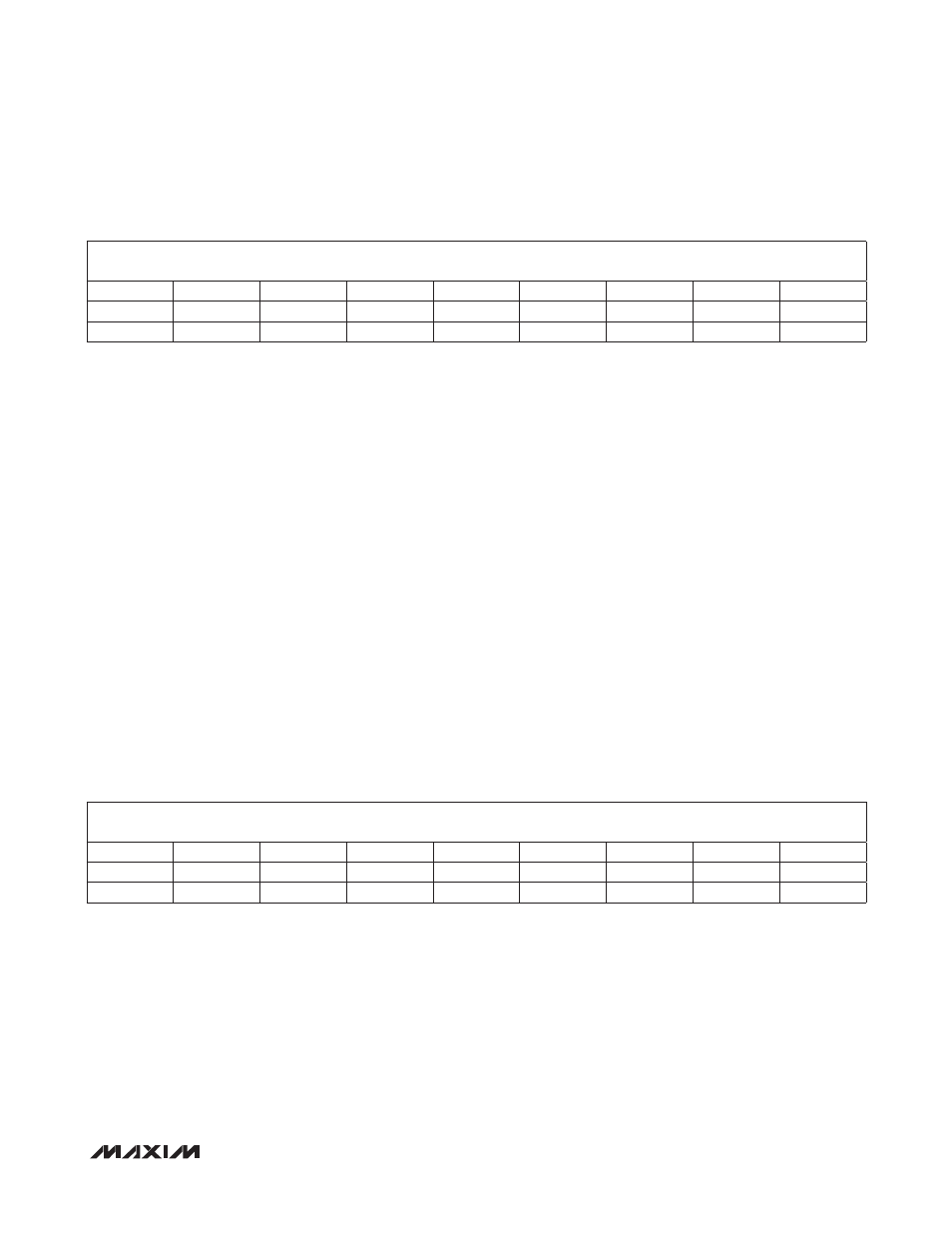
IrDA Register
FlowLvl—Flow Level Register
ADDRESS:
0x0E
MODE:
R/W
BIT
7
6
5
4
3
2
1
0
NAME
—
—
TxInv
RxInv
MIR
ShortIR
SIR
IrDAEn
RESET
0
0
0
0
0
0
0
0
ADDRESS:
0x0F
MODE:
R/W
BIT
7
6
5
4
3
2
1
0
NAME
Resume3
Resume2
Resume1
Resume0
Halt3
Halt2
Halt1
Halt0
RESET
0
0
0
0
0
0
0
0