Application issues – Rainbow Electronics MAX1717 User Manual
Page 28
MAX1717
Dynamically Adjustable, Synchronous
Step-Down Controller for Notebook CPUs
28
______________________________________________________________________________________
Application Issues
Voltage Positioning and
Effective Efficiency
Powering new mobile processors requires new tech-
niques to reduce cost, size, and power dissipation.
Voltage positioning reduces the total number of output
capacitors to meet a given transient response require-
ment. Setting the no-load output voltage slightly higher
allows a larger step down when the output current sud-
denly increases, and regulating at the lower output volt-
age under load allows a larger step up when the output
current suddenly decreases. Allowing a larger step size
means that the output capacitance can be reduced
and the capacitor’s ESR can be increased.
The no-load output voltage is raised by adding a fixed
offset to GNDS through a resistor divider from REF. A
27mV nominal value is appropriate for 1.6V applications.
This 27mV corresponds to a 0.9 x 27mV = 24mV =
1.5% increase with a V
OUT
of 1.6V. In the voltage-posi-
tioned circuit (Figure 3), this is realized with resistors R4
and R5. Use a 10µA resistor divider current.
Adding a series output resistor positions the full-load out-
put voltage below the actual DAC programmed voltage.
Connect FB and FBS directly to the inductor side of the
voltage-positioning resistor (R6, 5m
Ω). The other side of
the voltage-positioning resistor should be tied directly to
the output filter capacitor with a short, wide PC board
trace. With a 14A full-load current, R6 causes a 70mV
drop. This 70mV is a -4.4% error, but it is compensated
by the +1.5% error from the GNDS offset, resulting in a
net error of -2.9%. This is well within the typical specifica-
tion for voltage accuracy.
An additional benefit of voltage positioning is reduced
power consumption at high load currents. Because the
output voltage is lower under load, the CPU draws less
current. The result is lower power dissipation in the
CPU, though some extra power is dissipated in R6. For
a nominal 1.6V, 12A output, reducing the output volt-
age 2.9% gives an output voltage of 1.55V and an out-
put current of 11.65A. Given these values, CPU power
consumption is reduced from 19.2W to 18.1W. The
additional power consumption of R6 is:
5m
Ω x 11.65A
2
= 0.68W
and the overall power savings is as follows:
19.2 - (18.1 + 0.68) = 0.42W
In effect, 1W of CPU dissipation is saved and the power
supply dissipates much of the savings, but both the net
savings and the transfer of dissipation away from the
hot CPU are beneficial.
Effective efficiency is defined as the efficiency required
of a nonvoltage-positioned circuit to equal the total dis-
sipation of a voltage-positioned circuit for a given CPU
operating condition.
Calculate effective efficiency as follows:
1) Start with the efficiency data for the positioned circuit
(V
IN
, I
IN
, V
OUT
, I
OUT
).
2) Model the load resistance for each data point:
R
LOAD
= V
OUT
/ I
OUT
3) Calculate the output current that would exist for each
R
LOAD
data point in a nonpositioned application:
I
NP
= V
NP
/ R
LOAD
where V
NP
= 1.6V (in this example).
4) Calculate effective efficiency as:
Effective efficiency = (V
NP
x I
NP
) / (V
IN
x I
IN
) =
calculated nonpositioned power output divided by
the measured voltage-positioned power input.
5) Plot the efficiency data point at the nonpositioned
current, I
NP
.
The effective efficiency of voltage-positioned circuits is
shown in the Typical Operating Characteristics.
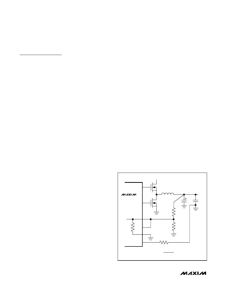
DL
DH
FB
FBS
GNDS
V
BATT
V
OUT
R1
1k
Ω
R2
180k
Ω
MAX1717
V
OUT
= V
FB
x
(
1 +
)
R1
R2 || 180k
Ω
R2
GND
Figure 11. Adjusting V
OUT
with a Resistor-Divider