Rainbow Electronics MAX1717 User Manual
Page 18
MAX1717
Dynamically Adjustable, Synchronous
Step-Down Controller for Notebook CPUs
18
______________________________________________________________________________________
Forced-PWM Mode (SKP/
SDN
Open)
The low-noise forced-PWM mode (SKP/SDN open) dis-
ables the zero-crossing comparator that controls the
low-side switch on-time. This causes the low-side gate-
drive waveform to become the complement of the high-
side gate-drive waveform. This in turn causes the
inductor current to reverse at light loads as the PWM
loop strives to maintain a duty ratio of V
OUT
/V
BATT
. The
benefit of forced-PWM mode is to keep the switching
frequency fairly constant, but it comes at a cost: the no-
load battery current can be 10mA to 40mA, depending
on the external MOSFETs and switching frequency.
Forced-PWM mode is most useful for reducing audio-
frequency noise and improving the cross-regulation of
multiple-output applications that use a flyback trans-
former or coupled inductor.
Current-Limit Circuit
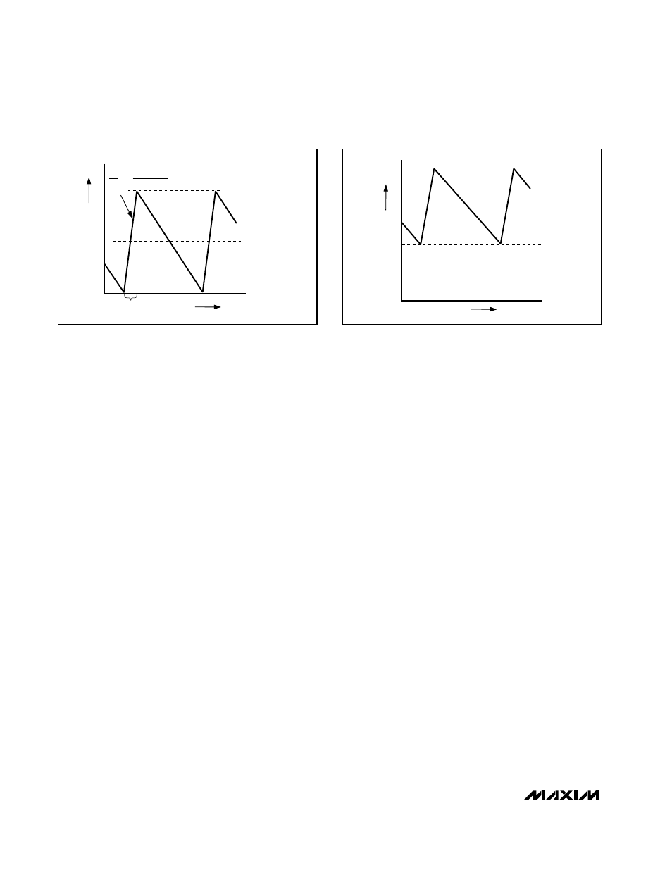
The current-limit circuit employs a unique “valley” current-
sensing algorithm that uses the on-resistance of the
low-side MOSFET as a current-sensing element. If the
current-sense signal is above the current-limit thresh-
old, the PWM is not allowed to initiate a new cycle
(Figure 5). The actual peak current is greater than the
current-limit threshold by an amount equal to the induc-
tor ripple current. Therefore, the exact current-limit
characteristic and maximum load capability are a func-
tion of the MOSFET on-resistance, inductor value, and
battery voltage. The reward for this uncertainty is
robust, lossless overcurrent sensing. When combined
with the undervoltage protection circuit, this current-
limit method is effective in almost every circumstance.
There is also a negative current limit that prevents exces-
sive reverse inductor currents when V
OUT
is sinking cur-
rent. The negative current-limit threshold is set to approxi-
mately 120% of the positive current limit, and therefore
tracks the positive current limit when ILIM is adjusted.
The current-limit threshold is adjusted with an external
resistor-divider at ILIM. The current-limit threshold
adjustment range is from 50mV to 300mV. In the
adjustable mode, the current-limit threshold voltage is
precisely 1/10th the voltage seen at ILIM. The threshold
defaults to 100mV when ILIM is connected to V
CC
. The
logic threshold for switchover to the 100mV default
value is approximately V
CC
- 1V.
The adjustable current limit accommodates MOSFETs
with a wide range of on-resistance characteristics (see
the Design Procedure section).
Carefully observe the PC board layout guidelines to
ensure that noise and DC errors don’t corrupt the cur-
rent-sense signals seen by LX and GND. Place the IC
close to the low-side MOSFET with short, direct traces,
making a Kelvin sense connection to the source and
drain terminals.
MOSFET Gate Drivers (DH, DL)
The DH and DL drivers are optimized for driving mod-
erate-sized high-side and larger low-side power
MOSFETs. This is consistent with the low duty factor
seen in the notebook CPU environment, where a large
V
BATT
- V
OUT
differential exists. An adaptive dead-time
circuit monitors the DL output and prevents the high-
side FET from turning on until DL is fully off. There must
be a low-resistance, low-inductance path from the DL
driver to the MOSFET gate for the adaptive dead-time cir-
cuit to work properly. Otherwise, the sense circuitry in the
MAX1717 will interpret the MOSFET gate as “off” while
there is actually still charge left on the gate. Use very
INDUCTOR CURRENT
I
LOAD
= I
PEAK
/2
ON-TIME
0
TIME
-I
PEAK
L
V
BATT
- V
OUT
∆i
∆t
=
Figure 4. Pulse-Skipping/Discontinuous Crossover Point
INDUCTOR CURRENT
I
LIMIT
I
LOAD
0
TIME
-I
PEAK
Figure 5. “Valley” Current-Limit Threshold Point