Rainbow Electronics MAX1717 User Manual
Page 22
MAX1717
Dynamically Adjustable, Synchronous
Step-Down Controller for Notebook CPUs
22
______________________________________________________________________________________
Output Voltage Transition Timing
The MAX1717 is designed to perform output voltage
transitions in a controlled manner, automatically mini-
mizing input surge currents. This feature allows the cir-
cuit designer to achieve nearly ideal transitions,
guaranteeing just-in-time arrival at the new output volt-
age level with the lowest possible peak currents for a
given output capacitance. This makes the IC very suit-
able for CPUs featuring SpeedStep technology and
other ICs that operate in two or more modes with differ-
ent core voltage levels.
Intel’s mobile Pentium III CPU with SpeedStep technol-
ogy operates at two distinct clock frequencies and
requires two distinct core voltages. When transitioning
from one clock frequency to the other, the CPU first
goes into a low-power state, then the output voltage
and clock frequency are changed. The change must
be accomplished in 100µs or the system may halt.
At the beginning of an output voltage transition, the
MAX1717 brings the VGATE output low, indicating that
a transition is beginning. VGATE remains low during the
transition and goes high when the slew-rate controller
has set the internal DAC to the final value and one
additional slew-rate clock period has passed. The slew-
rate clock frequency (set by resistor R
TIME
) must be set
fast enough to ensure that VGATE goes high within the
allowed 100µs. Alternatively, the slew-rate clock can be
set faster than necessary and VGATE’s rising edge can
be detected so that normal system operation can
resume even earlier.
The output voltage transition is performed in 25mV
steps, preceded by a 4µs delay and followed by one
additional clock period after which VGATE goes high if
the output voltage is in regulation. The total time for a
transition depends on R
TIME
, the voltage difference,
and the accuracy of the MAX1717’s slew-rate clock,
and is not dependent on the total output capacitance.
The greater the output capacitance, the higher the
surge current required for the transition. The MAX1717
will automatically control the current to the minimum
level required to complete the transition in the calculat-
ed time, as long as the surge current is less than the
current limit set by ILIM.
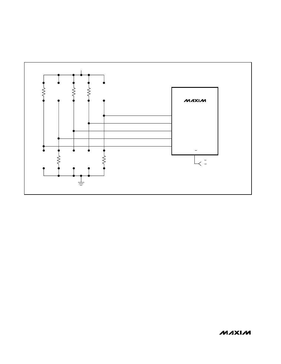
MAX1717
D4
D3
D2
D1
D0
A/B
A/B = LOW = 1.60V
A/B = HIGH = 1.35V
1k
Ω
1k
Ω
1k
Ω
1k
Ω
100k
Ω
2.7V TO 5.5V
NOTE: USE PULLUP FOR A-MODE 1, PULLDOWN FOR A-MODE 0.
USE
≥ 100kΩ FOR B-MODE 1, ≤ 1kΩ FOR B-MODE 0.
Figure 9. Using the Internal Mux with Both VID Codes Resistor Programmed