Rainbow Electronics MAX1717 User Manual
Page 17
MAX1717
Dynamically Adjustable, Synchronous
Step-Down Controller for Notebook CPUs
______________________________________________________________________________________
17
For a battery range of 7V to 24V, this threshold is rela-
tively constant, with only a minor dependence on bat-
tery voltage:
where K is the on-time scale factor (Table 3). The load-
current level at which PFM/PWM crossover occurs,
I
LOAD(SKIP)
, is equal to 1/2 the peak-to-peak ripple cur-
rent, which is a function of the inductor value (Figure 4).
For example, in the standard application circuit this
becomes:
The crossover point occurs at an even lower value if a
swinging (soft-saturation) inductor is used.
The switching waveforms may appear noisy and asyn-
chronous when light loading causes pulse-skipping
operation, but this is a normal operating condition that
results in high light-load efficiency. Trade-offs in PFM
noise vs. light-load efficiency are made by varying the
inductor value. Generally, low inductor values produce
a broader efficiency vs. load curve, while higher values
result in higher full-load efficiency (assuming that the
coil resistance remains fixed) and less output voltage
ripple. Penalties for using higher inductor values
include larger physical size and degraded load-tran-
sient response (especially at low input voltage levels).
3 3
1 6
2
1
12
1 6
12
2 3
.
.
.
.
µ
µ
s
V
H
V
V
V
A
Ч
Ч
Ч
=
−
I
K
V
L
V
V
V
LOAD SKIP
OUT
BATT
OUT
BATT
(
)
≈
Ч
Ч
Ч
−
2
V
CC
V
BATT
+5V
BIAS SUPPLY
C2
POWER-GOOD
INDICATOR
L1
1
µH
R6
0.005
Ω
SKP/SDN
V+
22
1
2
3
21
20
19
18
24
23
14
13
4
5
11
12
7
15
D2
CMPSH-3
C6
1
µF
C7
0.1
µF
C4
1
µF
C3
470pF
TO V
CC
Q1
D1
R2
100k
Ω
Q2
C5
1
µF
R1
20
Ω
C1
D0
TIME
D1
D2
ON/OFF
CONTROL
DL
LX
BST
DH
GND
FB
FBS
GNDS
D1 = INTL RECT 10MQ040N.
FOR OTHER COMPONENTS,
SEE TABLE 1 VALUES.
VGATE
V
DD
MAX1717
8
9
6
10
+5V
16
D3
17
D4
TON
REF
CC
A/B
ILIM
R7
120k
Ω
100k
Ω
TO V
CC
HIGH/LOW
R4
2k
Ω
R5
150k
Ω
TO V
REF
A/B = LOW = 1.60V
A/B = HIGH = 1.35V
V
OUT
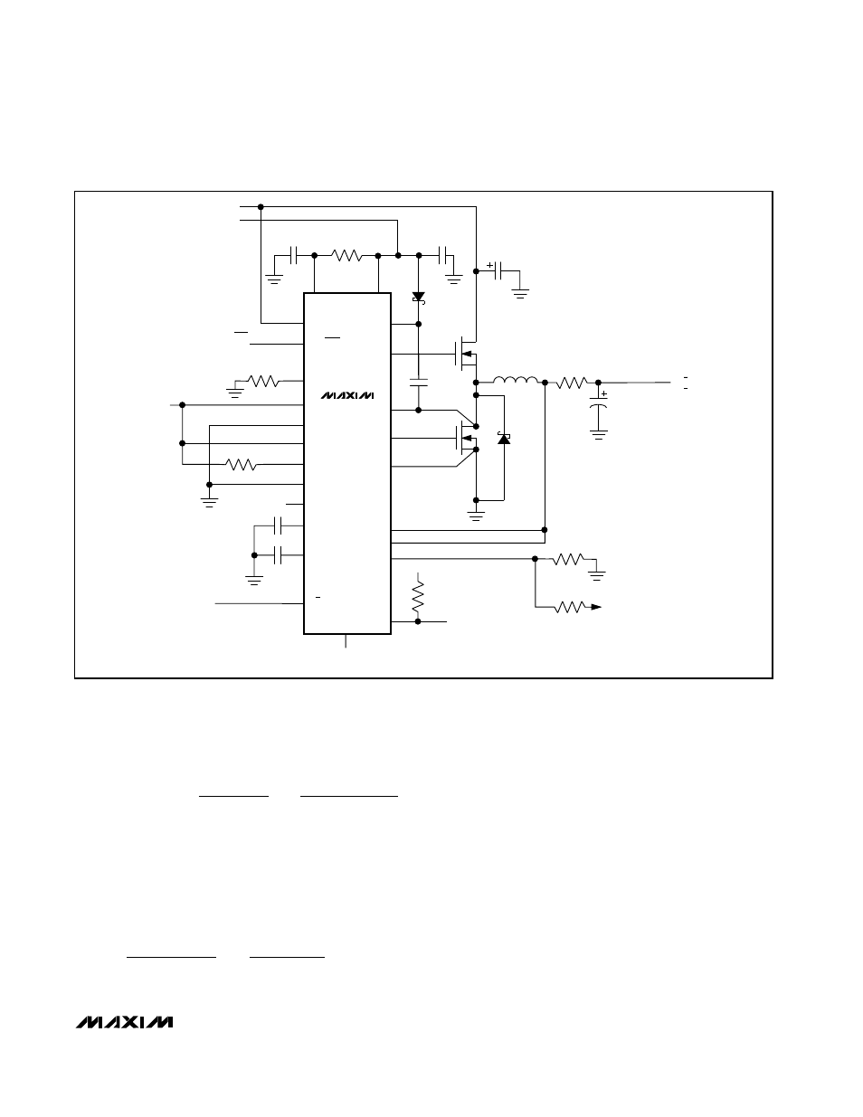
Figure 3. Voltage-Positioned Circuit