Detailed description – Rainbow Electronics MAX1717 User Manual
Page 14
MAX1717
Dynamically Adjustable, Synchronous
Step-Down Controller for Notebook CPUs
14
______________________________________________________________________________________
Detailed Description
+5V Bias Supply (V
CC
and V
DD
)
The MAX1717 requires an external +5V bias supply in
addition to the battery. Typically, this +5V bias supply
is the notebook’s 95% efficient +5V system supply.
Keeping the bias supply external to the IC improves
efficiency and eliminates the cost associated with the
+5V linear regulator that would otherwise be needed to
supply the PWM circuit and gate drivers. If stand-alone
capability is needed, the +5V supply can be generated
with an external linear regulator.
The +5V bias supply must provide V
CC
(PWM con-
troller) and V
DD
(gate-drive power), so the maximum
current drawn is:
I
BIAS
= I
CC
+ f (Q
G1
+ Q
G2
) = 10mA to 40mA (typ)
where I
CC
is 700µA (typ), f is the switching frequency,
and Q
G1
and Q
G2
are the MOSFET data sheet total
gate-charge specification limits at V
GS
= 5V.
V+ and V
DD
can be tied together if the input power
source is a fixed +4.5V to +5.5V supply. If the +5V bias
supply is powered up prior to the battery supply, the
enable signal (SKP/SDN going from low to high or
open) must be delayed until the battery voltage is pre-
sent to ensure startup.
Free-Running, Constant On-Time PWM
Controller with Input Feed-Forward
The Quick-PWM control architecture is a pseudofixed-
frequency, constant-on-time current-mode type with volt-
age feed-forward (Figure 2). This architecture relies on
the output filter capacitor’s ESR to act as the current-
sense resistor, so the output ripple voltage provides the
PWM ramp signal. The control algorithm is simple: the
high-side switch on-time is determined solely by a one-
shot whose period is inversely proportional to input volt-
age and directly proportional to output voltage. Another
one-shot sets a minimum off-time (400ns typ). The on-
time one-shot is triggered if the error comparator is low,
the low-side switch current is below the current-limit
threshold, and the minimum off-time one-shot has timed
out.
On-Time One-Shot (TON)
The heart of the PWM core is the one-shot that sets the
high-side switch on-time. This fast, low-jitter, adjustable
one-shot includes circuitry that varies the on-time in
response to battery and output voltage. The high-side
switch on-time is inversely proportional to the battery
voltage as measured by the V+ input, and proportional
to the output voltage. This algorithm results in a nearly
constant switching frequency despite the lack of a
fixed-frequency clock generator. The benefits of a con-
stant switching frequency are twofold: first, the frequency
can be selected to avoid noise-sensitive regions such
as the 455kHz IF band; second, the inductor ripple-cur-
rent operating point remains relatively constant, resulting
in easy design methodology and predictable output
voltage ripple.
On-Time = K (V
OUT
+ 0.075V) / V
IN
where K is set by the TON pin-strap connection and
0.075V is an approximation to accommodate the expect-
ed drop across the low-side MOSFET switch (Table 3).
The on-time one-shot has good accuracy at the operating
points specified in the Electrical Characteristics (±10% at
200kHz and 300kHz, ±12% at 550kHz and 1000kHz).
On-times at operating points far removed from the condi-
tions specified in the Electrical Characteristics can vary
over a wide range. For example, the 1000kHz setting will
typically run about 10% slower with inputs much greater
than +5V due to the very short on-times required.
On-times translate only roughly to switching frequencies.
The on-times guaranteed in the Electrical Character-
istics are influenced by switching delays in the external
high-side MOSFET. Resistive losses, including the
inductor, both MOSFETs, output capacitor ESR, and PC
board copper losses in the output and ground tend to
raise the switching frequency at higher output currents.
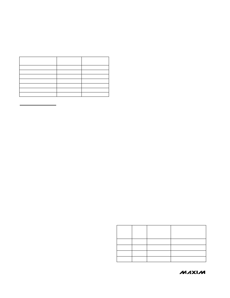
Table 2. Component Suppliers
Table 3. Approximate K-Factors Errors
±10
TON
SETTING
(kHz)
APPROXIMATE
K-FACTOR
ERROR (%)
MIN RECOMMENDED
V
BATT
AT V
OUT
= 1.6V
(V)
200
±10
2.1
300
2.3
550
±12.5
3.2
1000
±12.5
4.5
K
FACTOR
(µs)
5
3.3
1.8
1.0
MANUFACTURER
USA PHONE
FACTORY FAX
[Country Code]
Coilcraft
847-639-6400
[1] 847-639-1469
Dale-Vishay
402-564-3131
[1] 402-563-6418
[1] 310-322-3332
310-322-3331
International Rectifier
Kemet
408-986-0424
[1] 408-986-1442
[1] 714-373-7183
714-373-7939
Panasonic
[81] 3-3607-5144
847-956-0666
408-573-4150
[1] 408-573-4159
Sumida
Taiyo Yuden